
Large-visual-field high-resolution photoelectronic imaging system

A high-resolution, photoelectric imaging technology, applied in optics, optical components, beam optical fibers, etc., can solve the problems of low resolution, large volume, distortion, etc., and achieve the effect of high adaptability, small volume, and simple structure

Inactive Publication Date: 2014-12-24
SHANGHAI INST OF OPTICS & FINE MECHANICS CHINESE ACAD OF SCI
View PDF4 Cites 9 Cited by
  • Summary
  • Abstract
  • Description
  • Claims
  • Application Information

AI Technical Summary

Problems solved by technology

Prior art 1: wide-angle lens and fisheye lens, the field of view is large (fisheye lens can exceed 180 degrees), but the resolution is low, and fisheye lens has very large distortion (can exceed 100%); prior art 2: The panoramic optical system of reflection and refraction has a larger field of view, but the resolution is also low, and there is also very large distortion, the system is large in size, and the reflective imaging makes the application inconvenient; prior technology 3: (Multiscale gigapixel photography , NATURE, VOL.486, pp.386, 21JUNE, 2012), announced a large-field-of-view high-resolution imaging system similar to the present invention, but its system is relatively complicated, difficult to manufacture, and bulky

Method used


Image

  • Large-visual-field high-resolution photoelectronic imaging system
  • Large-visual-field high-resolution photoelectronic imaging system
  • Large-visual-field high-resolution photoelectronic imaging system

Examples


Embodiment Construction

[0027] The present invention will be further described below in conjunction with the accompanying drawings and embodiments, but the protection scope of the present invention should not be limited.

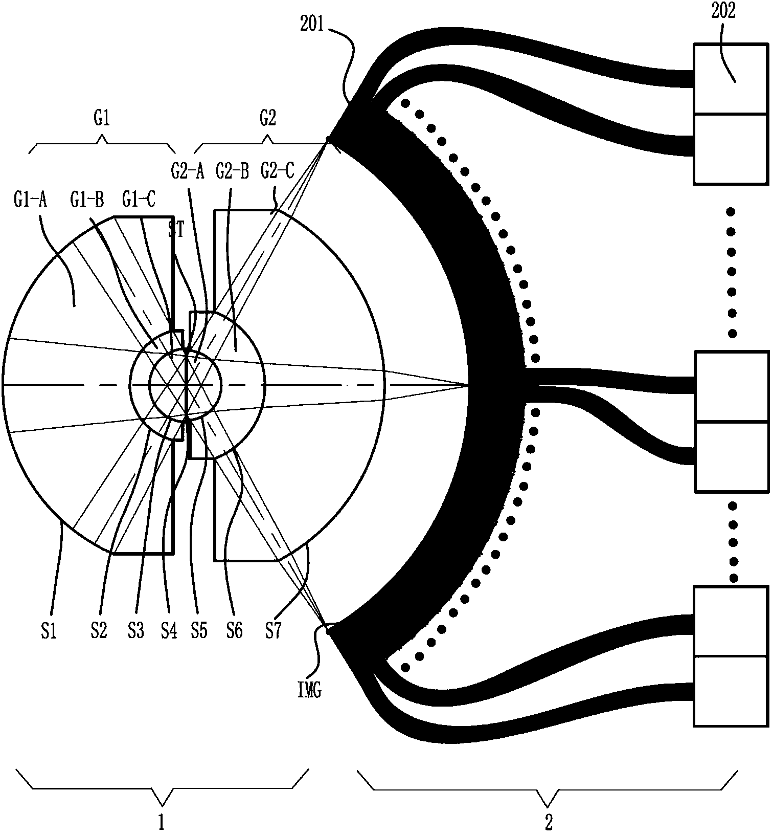
[0028] figure 1 It is a structural schematic diagram of Embodiment 1 of the large-field-of-view high-resolution photoelectric imaging system of the present invention. It can be seen from the figure that the large-field-of-view high-resolution photoelectric imaging system of the present invention consists of a concentric spherical lens 1 and a receiver array 2 .

[0029] The concentric spherical lens 1 is composed of a front group mirror G1, a stop ST and a rear group mirror G2, the front group mirror includes a lens G1-A, a lens G1-B and a lens G1-C, and the rear group The mirror includes lens G2-A, lens G2-B and lens G2-C. The lenses G1-A, G1-B, G1-C, G2-A, G2-B and G2-C are coaxial and glued in turn Connect together to form optical surfaces S1, S2, S3, S4, S5, S6, S7. The optica...


PUM


Abstract

The invention provides a large-visual-field high-resolution photoelectronic imaging system. The system is characterized by comprising a concentric sphere lens and a receiver array. Compared with a traditional imaging system, the system has the advantages of being large in single-shot imaging field and high in resolution ratio. In fact, for the single-shot imaging information amount, the system is capable of achieving the imaging capacity reaching hundreds of G pixels.

Description

technical field [0001] The invention belongs to the field of photoelectric imaging, in particular to a high-resolution photoelectric imaging system with a large field of view, which can perform high-resolution simultaneous imaging of a field of view close to 180 degrees, and is suitable for observation of the ground, the sea, and the sky at a fixed location , and vehicle-mounted, ship-mounted, and airborne mobile observations to achieve civilian, police, and military purposes. Background technique [0002] For an optical imaging system, under the premise of high resolution, its field of view can be expanded by moving or scanning, but there is a problem of poor timeliness. For example, as a satellite payload, it is necessary for the satellite to circle the earth many times before it can image a large area; when it is carried on an aircraft, there is a similar situation. Not only that, but if it is a military reconnaissance, observing the same place for a long time will cause ...

Claims


Application Information

Patent Timeline
Patent Type & Authority Applications(China)
IPC IPC(8): G02B27/00G02B6/06
Inventor 徐文东赵成强
Owner SHANGHAI INST OF OPTICS & FINE MECHANICS CHINESE ACAD OF SCI
Learn More