Polarization spectrum imaging device and method based on M-Z interference

A polarization spectrum and imaging device technology, which is applied in the direction of interference spectroscopy, polarization spectrum, and measurement devices, can solve the problems of unsuitable measurement conditions for rapid changes in polarization state information, inability to measure dynamic targets in real time, and low energy utilization. Achieve the effects of convenient imaging, strong suppression ability, and high energy utilization

Inactive Publication Date: 2020-09-25
XI'AN INST OF OPTICS & FINE MECHANICS - CHINESE ACAD OF SCI
View PDF5 Cites 2 Cited by
  • Summary
  • Abstract
  • Description
  • Claims
  • Application Information

AI Technical Summary

Problems solved by technology

[0013] The present invention aims to solve the problem that the existing polarization spectrum imaging detection system and its corresponding method exist or cannot be used for real-time measurement of dynamic targets, or are not suitable for the measurement conditions of rapid changes in polarization state information, or need to set slits in the detection system, resulting in The energy utilization rate is low, or there is a technical problem of aliasing in the spectrum, and a polarization spectrum imaging device and method based on M-Z interference (ie Mach-Zehnder interference) is provided

Method used


Image

  • Polarization spectrum imaging device and method based on M-Z interference
  • Polarization spectrum imaging device and method based on M-Z interference
  • Polarization spectrum imaging device and method based on M-Z interference

Examples


Embodiment Construction

[0043] The technical solutions of the present invention will be clearly and completely described below in conjunction with the embodiments of the present invention and the accompanying drawings. Apparently, the described embodiments do not limit the present invention.

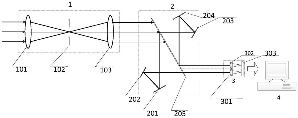
[0044] Such as Figure 1 to Figure 3 , the present invention provides a polarization spectrum imaging device based on M-Z interference, including a front optical telescopic system 1 , an interference beam splitting system 2 , a polarization beam splitting system 3 and an acquisition processing unit 4 .

[0045] Among them, the front optical telescopic system 1 is used to realize the front collection of target reflected light, field of view adjustment and collimated output, including front mirror group 101, field diaphragm 102 and collimator mirror group 103; interference beam splitting system 2 is used to realize the generation of interference conditions of parallel incident light beams, including a beam splitt...


PUM


Abstract

The invention belongs to a polarization spectrum imaging device and method. The objective of the invention is to solve the problems that existing polarization spectrum imaging detection systems and corresponding methods have problems or cannot be used for real-time measurement of a dynamic target, or are not suitable for measurement conditions of rapid change of polarization state information, ora slit needs to be arranged in the detection system. The invention provides a polarization spectrum imaging device and method based on M-Z interference. The device comprises a collecting and processing unit, and a front optical telescopic system, an interference light splitting system and a polarization light splitting system sequentially arranged. The imaging method is based on the device, targetreflected light is collected by the front lens group and the field diaphragm in a front-mounted mode, the field is adjusted, then the target reflected light is collimated and emitted by the collimating lens group, and after passing through the beam splitter, the reflected light is reflected by the first reflector and the second reflector in sequence, penetrates through the beam splitter and enters the Fourier mirror array. The transmission light is reflected by the third reflector, the fourth reflector and the beam splitter in sequence and then enters the Fourier mirror array, and polarization interference fringes are generated on the detector through the polarization diaphragm.

Description

technical field [0001] The invention relates to a polarization spectrum imaging device and method, in particular to a polarization spectrum imaging device and method based on M-Z interference. Background technique [0002] The combination of spectral imaging and polarization imaging forms a new optical remote sensing technology, that is, polarization spectral imaging technology. This technology is a new type of detection technology that can integrate image information, spectral information and polarization state information of the target, and has obvious advanced principles and technical advantages. [0003] The best detection and identification capabilities are achieved when polarization information is added to the image and spectral information. Especially suitable for target detection in turbid media, such as smoke, fog, haze, dust, turbid water, etc., coupled with the characteristics of "strong light weakening" and "weak light strengthening" of the polarization state, i...

Claims


Application Information

Patent Timeline
Patent Type & Authority Applications(China)
IPC IPC(8): G01J3/447G01J3/45G01J3/28G01J3/02
CPCG01J3/447G01J3/45G01J3/2823G01J3/0224G01J3/0208
Inventor 于涛刘嘉诚胡炳樑刘宏王雪霁刘骁张周锋
Owner XI'AN INST OF OPTICS & FINE MECHANICS - CHINESE ACAD OF SCI
Why Eureka
Try Eureka