
Improved cell glue injection device

A glue injection device and an improved technology, which is applied in the direction of alkaline storage batteries, battery pack parts, battery boxes/coats, etc., can solve the problems of easy damage of sealing rings, inability to spread evenly, inconvenient maintenance, etc., and achieve structural design Simple, improve work efficiency, reasonable structure and layout effect

Active Publication Date: 2014-12-24
NINGBO BEITERUI ENERGY TECH
View PDF5 Cites 24 Cited by
  • Summary
  • Abstract
  • Description
  • Claims
  • Application Information

AI Technical Summary

Problems solved by technology

The structure of the battery glue injection device in the prior art is realized by a high temperature resistant glue injection valve body, which is expensive and has multiple sealing rings inside to ensure its tightness
However, due to the high temperature and the special viscosity of the colloid, the sealing ring is easily damaged and inconvenient to maintain
And the weight cannot be adjusted. The current weight is adjusted by the length of the glue injection time, which is extremely unstable.
Furthermore, since the current injection of colloid is not achieved by air pressure, the injected colloid will accumulate in the middle of the bottom of the battery steel case like water droplets, and cannot be spread evenly, resulting in unsatisfactory injection effect

Method used


Image

  • Improved cell glue injection device
  • Improved cell glue injection device
  • Improved cell glue injection device

Examples


Embodiment Construction

[0022] The following are specific embodiments of the present invention and in conjunction with the accompanying drawings, the technical solutions of the present invention are further described, but the present invention is not limited to these embodiments.

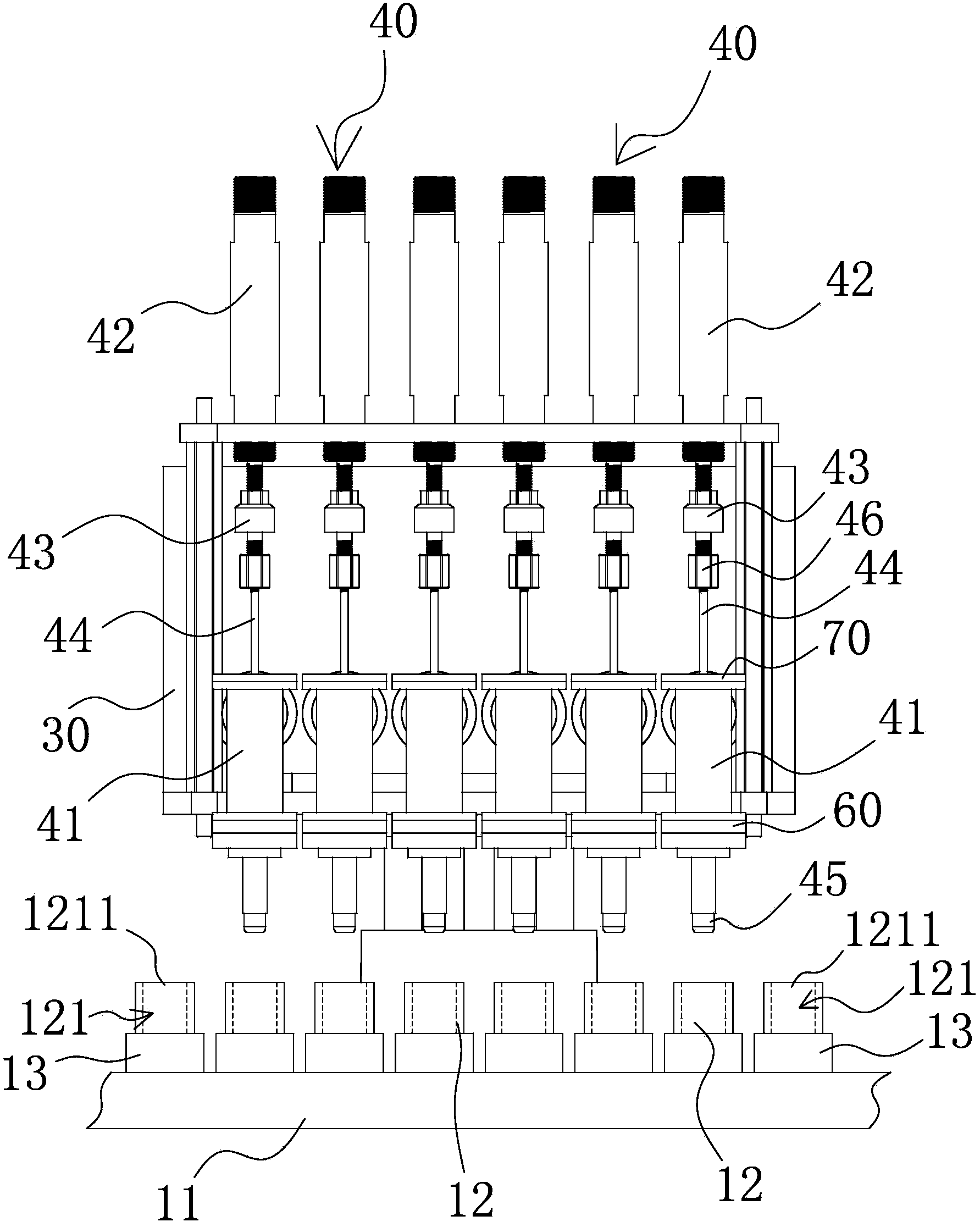
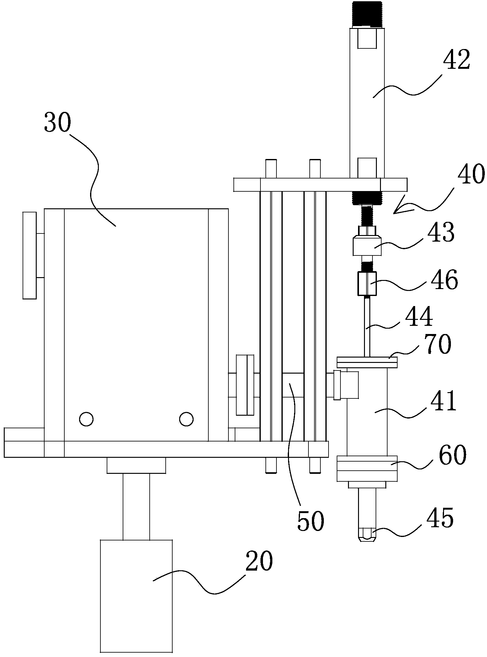
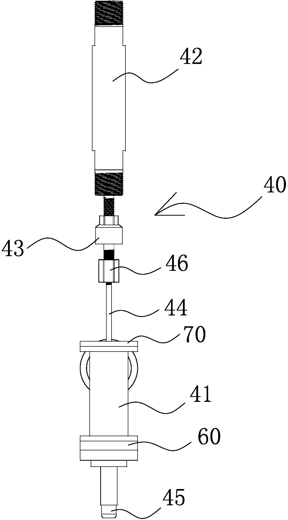
[0023] Such as Figure 1 to Figure 4 As shown, the improved battery glue injection device includes a carrier platform 20, a material tank 30 for storing glue, and a plurality of glue injection components 40 arranged in parallel at equal intervals. The material tank 30 is fixed on the carrier platform 20 and extends from the inside to the A stainless steel layer, a thermal insulation layer, and a shell layer are arranged on the outside in turn. The glue injection assembly 40 includes a glue injection pipe 41 fixed on the carrier 20 and a power part 42 corresponding to the glue injection pipe 41. In the middle of the glue injection pipe 41, there is a vertical The provided glue injection channel 411 and the glue injection ou...


PUM


Abstract

The invention provides an improved cell glue injection device and belongs to the technical field of cell production. The improved cell glue injection device comprises a bearing platform, a material tank for storing glue and multiple glue injection assemblies, wherein the material tank is fixedly arranged on the bearing platform; a stainless steel layer, a thermal insulating layer and a shell layer are arranged in sequence from inside to outside; each glue injection assembly comprises a glue injection pipe fixedly arranged on the bearing platform and a power element arranged corresponding to the glue injection pipe; a vertically arranged glue injection channel and a glue injection outlet communicated with the glue injection channel are formed in the middle part of the glue injection pipe; the material tank is communicated with each glue injection pipe and the glue can be conveyed to the corresponding glue injection channel; the tail end of the power element is connected with a glue injection pin rod through a floating joint; the glue injection pin rod and the glue injection channel are coaxially arranged; the power element is movably connected on the bearing platform, drives the glue injection pin rod to stretch into the glue injection channel and discharges the glue in the glue injection channel from the glue injection outlet. The improved cell glue injection device has the advantages of reasonable structure, economical efficiency and applicability and good glue injection effect.

Description

technical field [0001] The invention belongs to the technical field of battery production and relates to an improved battery glue injection device. Background technique [0002] With the advancement of battery technology, the production technology of alkaline batteries is becoming more and more mature, and the market demand is large. In some battery production lines, due to the relatively large volume of some batteries, it is relatively difficult to curl the head of the sealing end of the rolling paper inside. It is difficult to ensure that the sealing end of each battery steel case can be ironed firmly. If there is a gap in the seal of the diaphragm paper, the electrolyte will seep out after the electrolyte is injected, which will cause the battery to climb alkali, gas, and even cause the battery to explode, which is extremely dangerous. Therefore, a glue injection process needs to be added after the diaphragm paper is inserted. [0003] The glue injection process is the...

Claims


Application Information

Patent Timeline
IPC IPC(8): H01M10/28H01M2/08
CPCH01M50/183Y02E60/10Y02P70/50
Inventor 杨上华沈立忠洪孝梁
Owner NINGBO BEITERUI ENERGY TECH
Learn More