
A Circuit Alternative to Brush Structure in Slip Ring

A slip ring and brush technology, applied in circuits, current collectors, electrical components, etc., to reduce system power consumption, avoid dead drives, and ensure high-speed digital signal transmission rates

Inactive Publication Date: 2016-08-24
NINGBO CHENGDIAN TAIKE ELECTRONICS INFORMATION TECH DEV
View PDF3 Cites 0 Cited by
  • Summary
  • Abstract
  • Description
  • Claims
  • Application Information

AI Technical Summary

Problems solved by technology

In this circuit, optical communication is used to replace signal transmission, and wireless power transmission is used to replace electric power transmission. Therefore, the mechanical structure of the brush is replaced by the circuit structure, and the function of the brush is realized by using the circuit structure, which overcomes the difficulties in the use of the mechanical structure. problem, improve slip ring life and reliability

Method used


Image

  • A Circuit Alternative to Brush Structure in Slip Ring
  • A Circuit Alternative to Brush Structure in Slip Ring
  • A Circuit Alternative to Brush Structure in Slip Ring

Examples


Embodiment

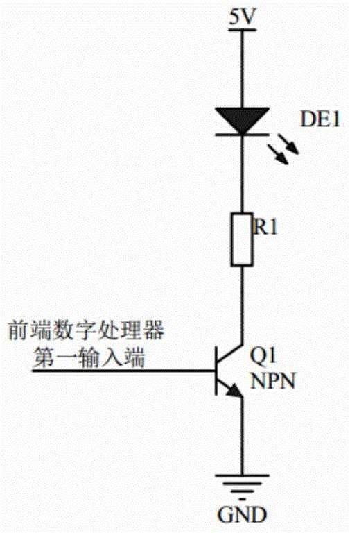
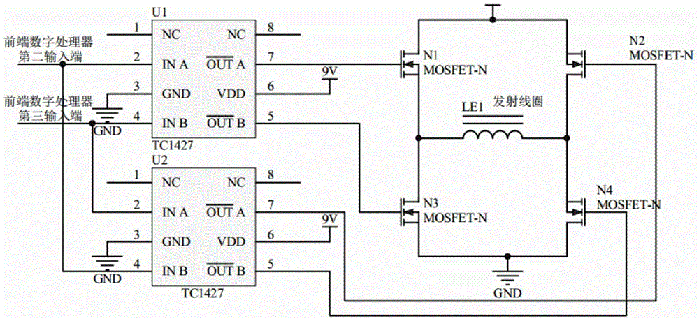
[0025] Example: such as figure 1 As shown, a circuit that replaces the brush structure in a slip ring includes a sending module and a receiving module. The sending module includes a front-end digital processor, an optical signal transmitter, and a wireless power transmitter. The front-end digital processor is arranged on the slip ring body The optical signal transmitter is installed outside the slip ring ring body, and the wireless power transmitter is installed outside the slip ring ring body. The front-end digital processor has three output terminals, which are the first output terminals for transmitting electrical signals. , The second output terminal for transmitting the first driving signal and the third output terminal for transmitting the second driving signal, the wireless power transmitter has two input terminals, respectively the first input for receiving the first driving signal Terminal and the second input terminal for receiving the second driving signal, the first ...


PUM


Abstract

The invention discloses a circuit for replacing an electric brush structure in a slip ring. The circuit comprises a transmitting module and a receiving module. The transmitting module comprises a front-end digital processor, an optical signal transmitter and a wireless power transmitter, wherein the front-end digital processor is provided with three output ends, the first output end is connected with the optical signal transmitter, and the second output end and the third output end are connected with the wireless power transmitter. The receiving module comprises an optical signal receiver, a rear-end digital processor, a wireless power receiver, a DC-DC converter and a power source, wherein the output end of the optical signal receiver is connected with the rear-end digital processor, the output end of the wireless power receiver is connected with the DC-DC converter, and space transmission is adopted between the wireless power transmitter and the wireless power receiver as well as between the optical signal transmitter and the optical signal receiver. The circuit for replacing the electric brush structure in the slip ring has the advantages that the electric brush structure in the traditional slip ring is replaced, the problems that due to the electric brush structure, heat dissipation is difficult, and friction loss is large are avoided, the service life of the slip ring is prolonged, and the reliability of the slip ring is improved.

Description

Technical field [0001] The invention relates to a circuit that replaces the brush structure in a slip ring, in particular to a circuit that uses wireless transmission instead of wired transmission. Background technique [0002] The existing slip ring belongs to the application category of contact sliding connection, also known as slip ring or adapter, which is a precision power transmission device that realizes the data signal and power transmission of two relative rotating mechanisms. The existing slip ring includes a slip ring ring body, multiple input wires, multiple output wires, multiple conductive rings, a brush holder and multiple brushes located in the slip ring ring body. The brush holder is a cantilever beam structure supported by a single end. It has multiple cantilevers. The number of input wires, output wires, conductive rings, brush holder cantilevers and brushes are the same. The brushes are installed on the top of the cantilever of the brush holder. Multiple condu...

Claims


Application Information

Patent Timeline
Patent Type & Authority Patents(China)
IPC IPC(8): H01R39/24
Inventor 段衍东田丹陈薇胡丽霞
Owner NINGBO CHENGDIAN TAIKE ELECTRONICS INFORMATION TECH DEV
Learn More