Singlet oxygen generator
A singlet oxygen generator technology, used in phonon exciters, lasers, oxygen preparation, etc., can solve the problems of the reaction efficiency to be improved, the technology is immature, the stability is poor, etc., and achieve long working time and high reaction efficiency. , The effect of high working stability
- Summary
- Abstract
- Description
- Claims
- Application Information
AI Technical Summary
Problems solved by technology
Method used
Image


Examples
Embodiment 1
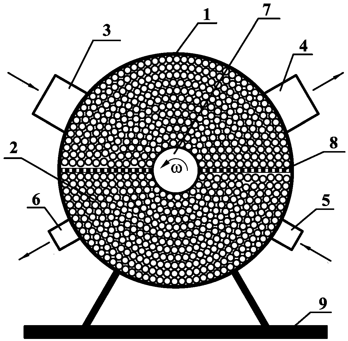
[0029] see figure 1 shown. The SOG is composed of a cavity 1 , a filler 2 , a gas inlet 3 , a gas outlet 4 , a reaction liquid inlet 5 , a reaction liquid outlet 6 , a rotating shaft 7 , blades 8 and a support 9 .
[0030] A kind of SOG applicable to COIL, which has a closed cylindrical generator cavity, a rotating shaft is arranged along the central axis of the cavity, and the two ends of the rotating shaft are rotatably connected to the two bottom walls of the cavity , blades are arranged on the rotating shaft, and the cavity is filled with fillers.
[0031] The central axis of the cavity is set along the horizontal direction, the upper side wall of the cavity is provided with a gas inlet and gas outlet, and the lower side wall of the cavity is provided with a reaction liquid inlet and a reaction liquid outlet.
[0032] In order to support and fix the SOG, a support is provided outside the cavity, and the cavity is fixed on the support.
[0033] In order to enable the fil...
Embodiment 2
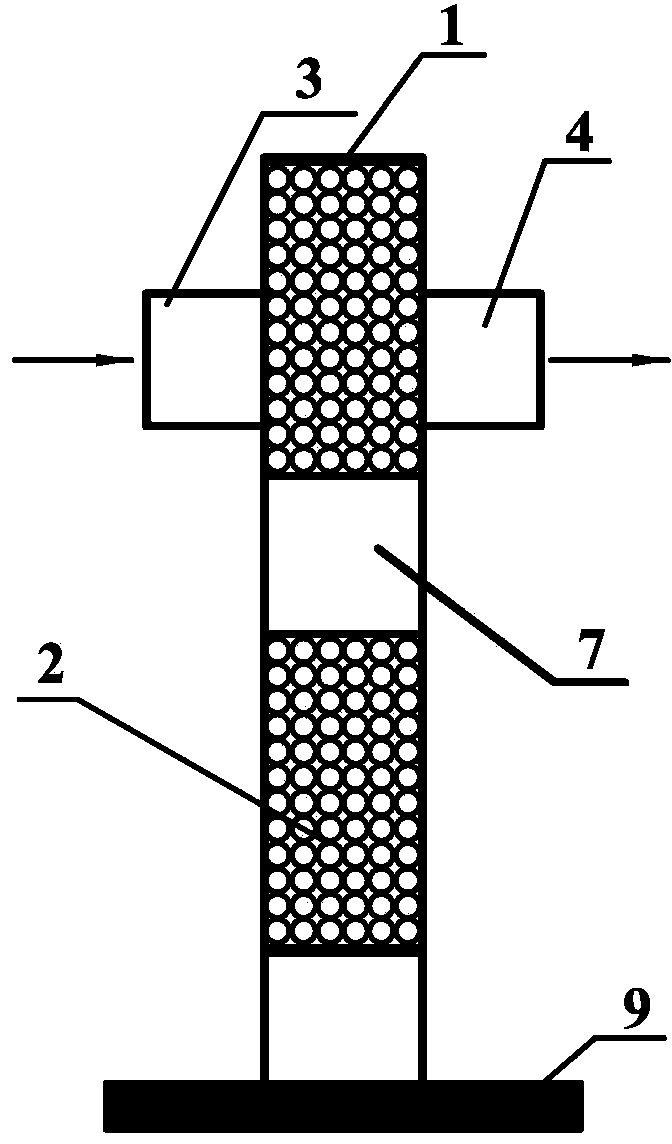
[0036] see figure 2 shown. figure 2 exist figure 1 Improved on the basis of the two, the basic structure of the two is the same, the difference is that the gas inlet 3 and the gas outlet 4 are from figure 1 The position of the side of the cavity 1 cylinder is moved to figure 2 Therefore, the direction of gas flow is perpendicular to the direction of movement of filler 2. Cl at gas inlet 3 2 The flow rate is 8mmol / s, and the total pressure obtained at the gas outlet 4 is greater than 3.3kPa, Cl 2 The utilization rate is greater than 80%, O 2 ( 1 Δ) The partial pressure is greater than 1.3kPa, O 2 ( 1 Δ) The yield is greater than 50% of O 2 ( 1 Δ) Airflow.
Embodiment 3
[0038] see figure 1 shown. This embodiment is basically the same as Embodiment 1, the difference is that the filler 2 is formed by winding a stainless steel ribbon with a thickness of 36 microns and a width of 1.5 mm filled in the cavity 1, and the specific surface area is greater than 10 cm. -1 . Cl at gas inlet 3 2 The flow rate is 10mmol / s, and the total pressure obtained at the gas outlet 4 is greater than 4.0kPa, Cl 2 The utilization rate is greater than 85%, O 2 ( 1 Δ) The partial pressure is greater than 1.7kPa, O 2 ( 1 Δ) The yield is greater than 50% of O 2 ( 1 Δ) Airflow.
PUM
| Property | Measurement | Unit |
|---|---|---|
| thickness | aaaaa | aaaaa |
| length | aaaaa | aaaaa |
Abstract
Description
Claims
Application Information
 - R&D
- Intellectual Property
- Life Sciences
- Materials
- Tech Scout
- Unparalleled Data Quality
- Higher Quality Content
- 60% Fewer Hallucinations
Browse by: Latest US Patents, China's latest patents, Technical Efficacy Thesaurus, Application Domain, Technology Topic, Popular Technical Reports.
© 2025 PatSnap. All rights reserved.Legal|Privacy policy|Modern Slavery Act Transparency Statement|Sitemap|About US| Contact US: help@patsnap.com