Eureka AIR delivers breakthrough ideas for toughest innovation challenges, trusted by R&D personnel around the world.

Solar energy and AC network collaborative charging system

An AC power grid and charging system technology, applied in battery circuit devices, current collectors, electric vehicles, etc., can solve the problems of fossil energy consumption and non-renewable fossil energy, reduce environmental pollution, save non-renewable energy, and have broad market applications Foreground effect

Inactive Publication Date: 2014-12-24
ZHEJIANG ENERGY & NUCLEAR TECH APPL RES INST
View PDF4 Cites 4 Cited by
  • Summary
  • Abstract
  • Description
  • Claims
  • Application Information

AI Technical Summary

Problems solved by technology

At present, it is generally charged with conventional electricity, which actually consumes conventional fossil energy, which cannot be regenerated.

Method used


Image

  • Solar energy and AC network collaborative charging system
  • Solar energy and AC network collaborative charging system
  • Solar energy and AC network collaborative charging system

Examples


Embodiment Construction

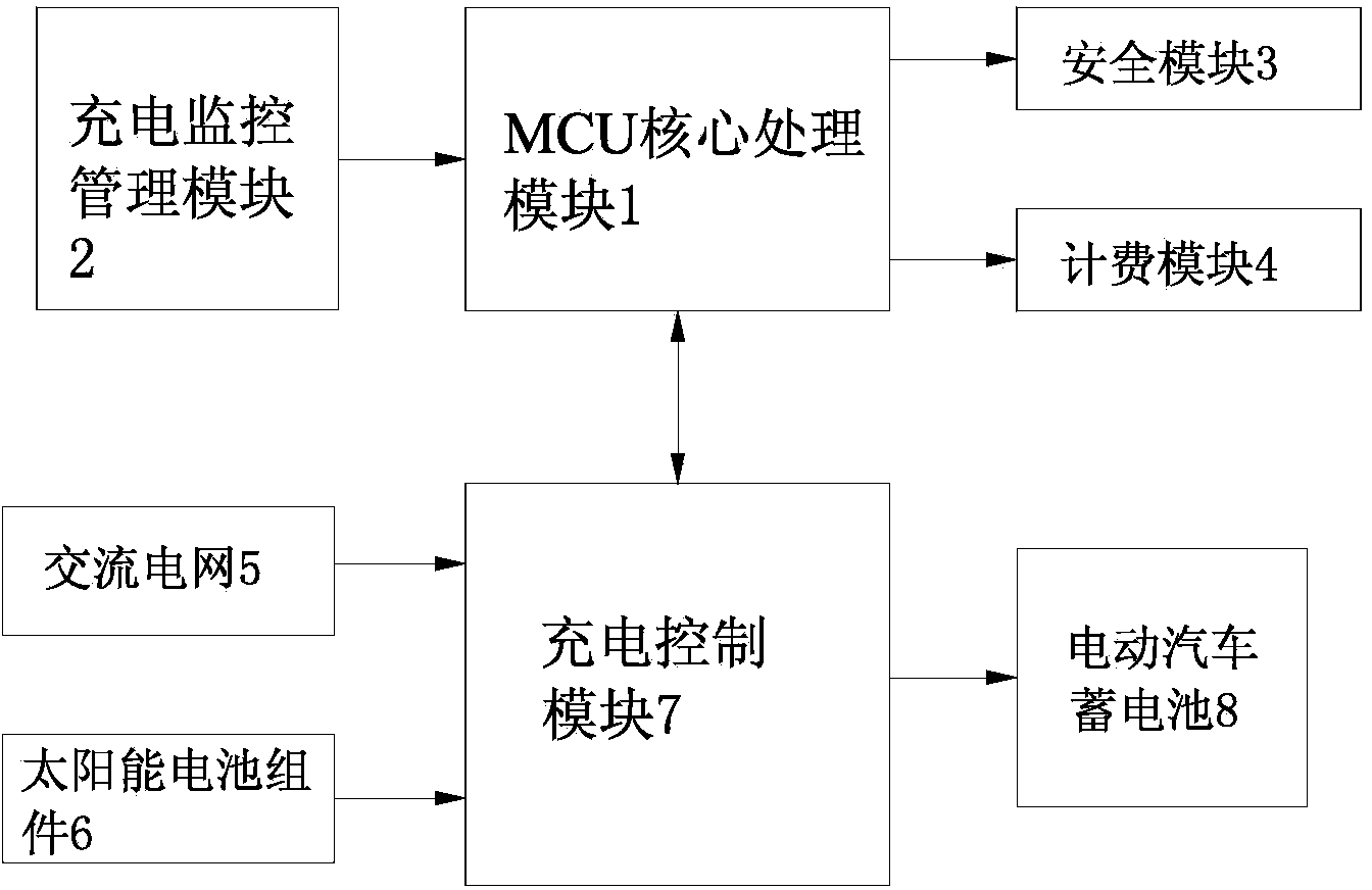
[0017] Such as figure 1 As shown, this embodiment is a solar energy and AC grid collaborative charging system, which is applied to electric vehicle charging stations, including MCU core processing module 1, charging monitoring and management module 2, security module 3, billing module 4, AC grid 5, The solar battery assembly 6 and the charging control module 7, the MCU core processing module 6 is connected with the charging monitoring management module circuit, the charging control module 7 is connected with the solar battery assembly 6, the AC grid 5 and the MCU core processing module 1 circuit.

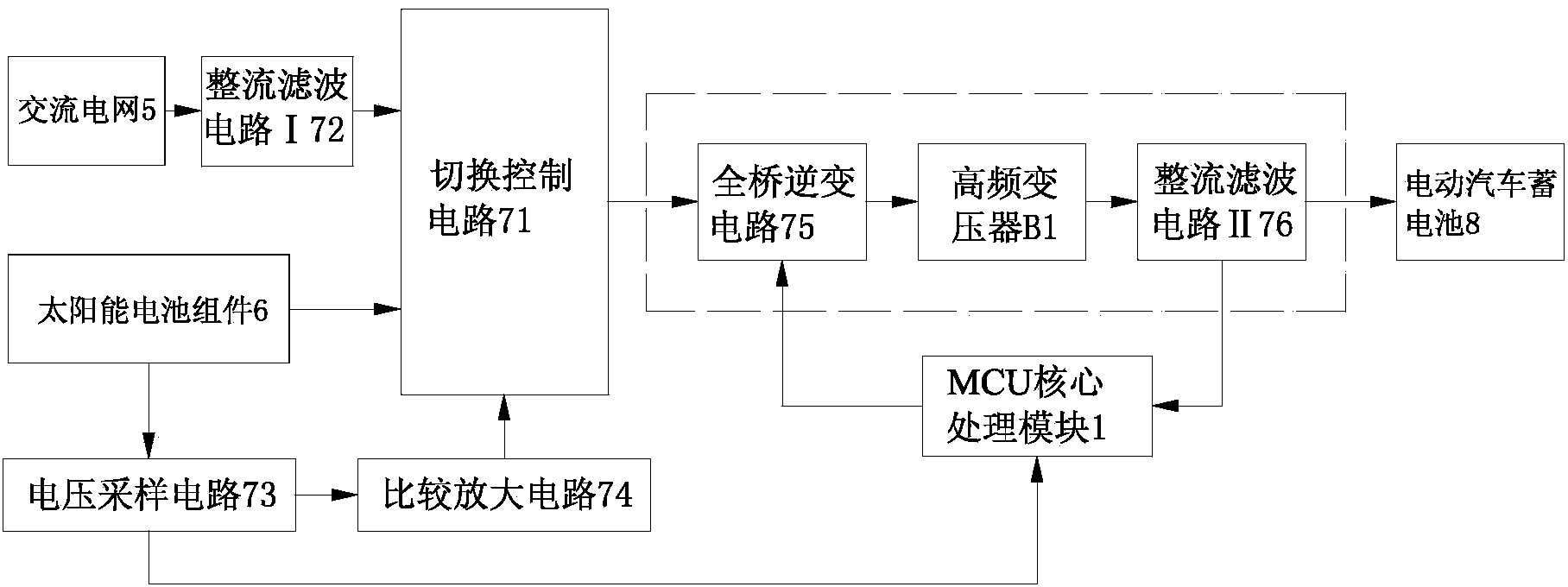
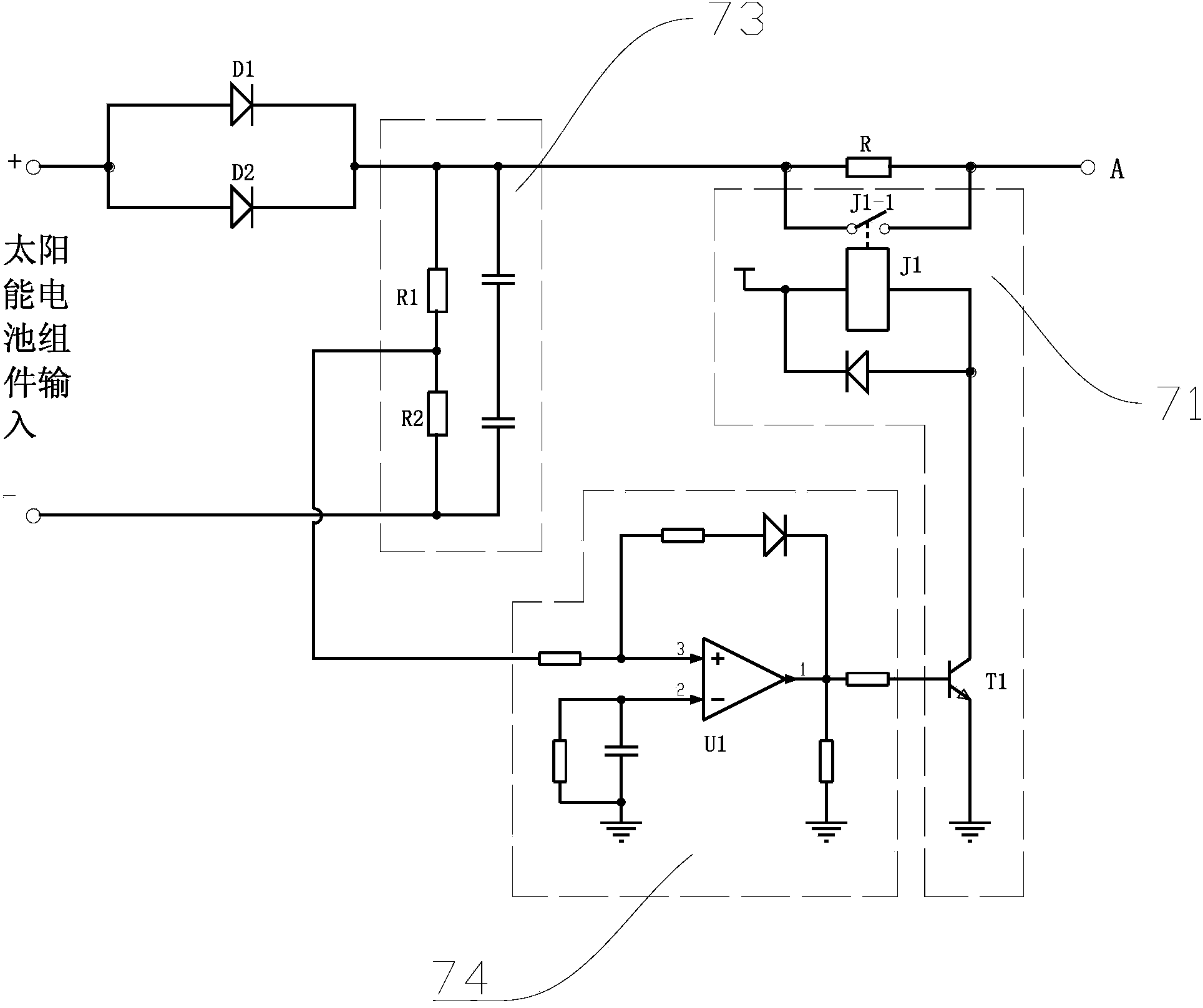
[0018] Such as figure 2 As shown, the charging control module 7 in this example is composed of a switching control circuit 71, a rectification and filtering circuit I72, a voltage sampling circuit 73, a comparison amplifier circuit 74 and a voltage stabilizing output circuit, wherein the solar battery module 6 is connected to the voltage stabilizing circuit via the switching contro...


PUM


Abstract

The invention relates to a solar energy and AC network collaborative charging system which is environmentally friendly, safe and reliable. Solar energy replaces conventional electric power for charging, plenty of no-renewable energy resources are saved, and environmental pollution is reduced. According to the technical scheme, the solar energy and AC network collaborative charging system comprises an AC network, an MCU core processing module and a charging monitoring management module. The MCU core processing module is electrically connected with the charging monitoring management module. The solar energy and AC network collaborative charging system is characterized in that the system further comprises a charge control module and a solar cell module. The charge control module is electrically connected with the solar cell module, the AC network and the MCU core processing module. The solar energy and AC network collaborative charging system is suitable for electric automobiles.

Description

technical field [0001] The invention relates to a coordinated charging system of solar energy and an AC power grid, which is suitable for electric vehicles. Background technique [0002] With the influence of the mass popularization of automobiles on the environment in our country, the current number of automobiles is an average of 10 automobiles per 1,000 people, but oil resources are insufficient, and tens of millions of tons of oil have been imported every year. In order to improve the utilization rate of oil, energy-saving and environmentally friendly electric vehicles have emerged as the times require. An important part of electric vehicles is the charging of energy storage. At present, it is generally charged with conventional electricity, which actually consumes conventional fossil energy, which cannot be regenerated. Contents of the invention [0003] The technical problem to be solved by the present invention is to provide a green, environmentally friendly, safe ...

Claims


Application Information

Patent Timeline
Patent Type & Authority Applications(China)
IPC IPC(8): H02J9/06H02J7/00
CPCY02B10/70
Inventor 朱正菲喻俊杜强
Owner ZHEJIANG ENERGY & NUCLEAR TECH APPL RES INST
Why Eureka
Eureka Blog
Learn More