
Two-point wireless transmitter and frequency offset correcting method thereof

A wireless transmitter, point-type technology, applied in the direction of angle modulation components, electrical components, transmission systems, etc., can solve the problems of large hardware resource consumption, high power consumption, etc., to reduce noise interference, improve stability, and improve transmission quality Effect

Inactive Publication Date: 2014-12-24
SHANGHAI PANCHIP MICROELECTRONICS CO LTD
View PDF5 Cites 12 Cited by
  • Summary
  • Abstract
  • Description
  • Claims
  • Application Information

AI Technical Summary

Problems solved by technology

[0008] Considering the above-mentioned deficiencies and demands of the existing wireless transmitters based on phase-locked loops, the present invention proposes a two-point wireless transmitter and its frequency offset calibration method to solve the problem of hardware resources during traditional two-point wireless transmitter frequency offset calibration. The problem of high consumption and high power consumption, while improving the quality of data transmission

Method used


Image

  • Two-point wireless transmitter and frequency offset correcting method thereof
  • Two-point wireless transmitter and frequency offset correcting method thereof
  • Two-point wireless transmitter and frequency offset correcting method thereof

Examples


Embodiment Construction

[0027] The present invention studies the circuit structure and functional characteristics of various traditional wireless transmitters based on phase-locked loops, explores their respective application deficiencies, and innovatively proposes a two-way transmitter that supports various data rate applications and has more stable performance. Point-type wireless transmitter, and maintain the reasonableness of power consumption, area and cost.

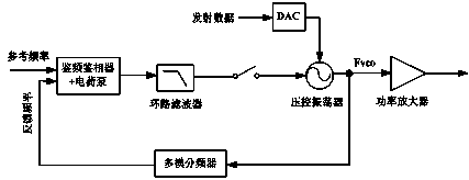
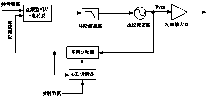
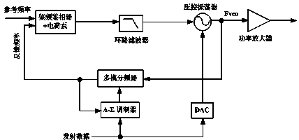
[0028] First understand the present invention from the circuit structure in conjunction with the accompanying drawings. Such as Image 6 with Figure 7 As shown, this two-point wireless transmitter is still formed based on a phase-locked loop circuit. The phase-locked loop circuit is composed of a frequency discriminator + a charge pump, a loop filter and a voltage-controlled oscillator, and the phase-locked loop is provided with a multi-mode frequency divider and a power amplifier. The signal input and output of the multi-mode frequenc...


PUM


Abstract

The invention discloses a two-point wireless transmitter and a frequency offset correcting method of the two-point wireless transmitter. Improvement is conducted based on a circuit structure of a traditional two-point transmitter, and frequency offset correction is achieved by conducting data interaction by means of two wireless communication chips which have the complete functional design and are successfully taped out. During implementation, the two chips are respectively provided with a microcontroller, a register, a transmitting module, a receiving module, an antenna and a change-over switch; transmitted data are input to the wireless transmitter through two paths, one path of data are input to a voltage-controlled oscillator through a branch switch S2 of the first chip and a DAC to be transmitted in an out-band mode, and the other path of data are input to a multi-mode frequency divider through a branch switch S1 of the first chip and a delta-sigma modulator for modulation and frequency division and then are transmitted in an in-band mode. According to the two-point wireless transmitter and the frequency offset correcting method of the two-point wireless transmitter, through the data interaction between the two chips and software processing of the microcontroller of the first chip, the frequency offset of the transmitted data can be corrected effectively, and high-quality smooth transmission of data is achieved; the two-point wireless transmitter and the frequency offset correcting method of the two-point wireless transmitter have the advantages that energy consumption is low, the number of hardware resources is small, cost is low and stability is high.

Description

technical field [0001] The invention relates to a wireless communication device, in particular to a wireless transmitter suitable for high-quality transmission in any data rate occasion with low energy consumption and low cost. Background technique [0002] At present, there are three main types of direct transmitters based on phase-locked loops commonly used: figure 1 Shown is an out-of-band transmitter based on a phase-locked loop, figure 2 Shown is an in-band transmitter based on a phase-locked loop, image 3 Shown is a two-point transmitter based on a phase-locked loop. [0003] The analysis circuit shows that the main disadvantages of the out-of-band transmitter based on the phase-locked loop: (1) Due to the low-pass characteristic of the loop filter of the phase-locked loop, the transmitter transmits out-of-band, supports high data rates, and does not support low The data rate is transmitted, so it will limit the application of the transmitter. (2) Since the trans...

Claims


Application Information

Patent Timeline
Patent Type & Authority Applications(China)
IPC IPC(8): H04B1/04H03C3/09
Inventor 时锴
Owner SHANGHAI PANCHIP MICROELECTRONICS CO LTD
Learn More