
Positioning and mounting system and positioning and mounting method used for engine timing system

A technology of positioning installation and timing system, applied in workpiece clamping devices, hand-held tools, manufacturing tools, etc., can solve the problems of difficulty in ensuring the installation accuracy of the timing system, low timing assembly accuracy, etc., and achieve improved timing. Assembly accuracy, the effect of eliminating assembly errors

Inactive Publication Date: 2014-12-31
北京汽车动力总成有限公司
View PDF8 Cites 12 Cited by
  • Summary
  • Abstract
  • Description
  • Claims
  • Application Information

AI Technical Summary

Problems solved by technology

[0004] During the above installation process, the timing assembly accuracy is not high. The existing assembly errors include the timing error caused by the elongation of the chain, the assembly error of the camshaft sprocket and the camshaft, the assembly error of the crankshaft sprocket and the crankshaft, and the timing system zero. Due to the manufacturing tolerances of the components themselves, it is difficult to guarantee the initial installation accuracy of the timing system

Method used


Image

  • Positioning and mounting system and positioning and mounting method used for engine timing system
  • Positioning and mounting system and positioning and mounting method used for engine timing system
  • Positioning and mounting system and positioning and mounting method used for engine timing system

Examples


Embodiment Construction

[0035] In order to make the technical problems, technical solutions and advantages to be solved by the embodiments of the present invention clearer, the following will describe in detail with reference to the drawings and specific embodiments.

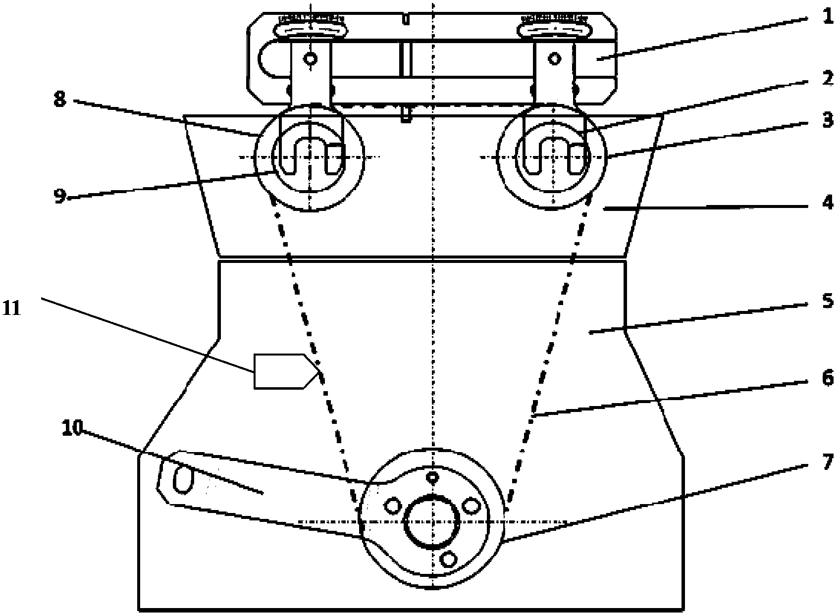
[0036] The specific embodiment of the present invention is used for the positioning installation system of engine timing system, and described engine comprises intake camshaft, intake camshaft sprocket, exhaust camshaft, exhaust camshaft sprocket, crankshaft, crankshaft sprocket, Timing chain, tappet and valve, the valve is connected with the intake camshaft and the exhaust camshaft through the tappet, wherein the positioning installation system includes:

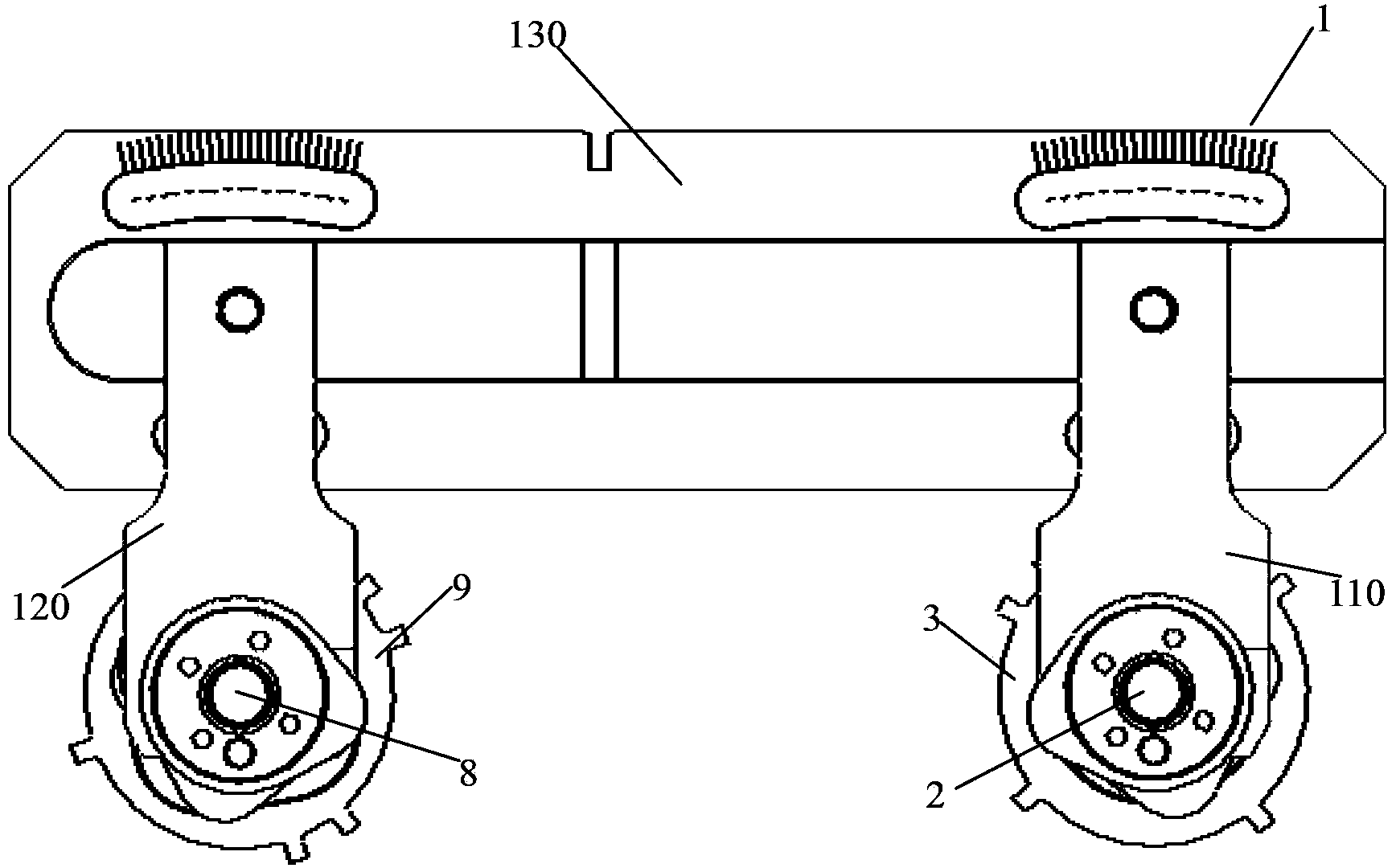
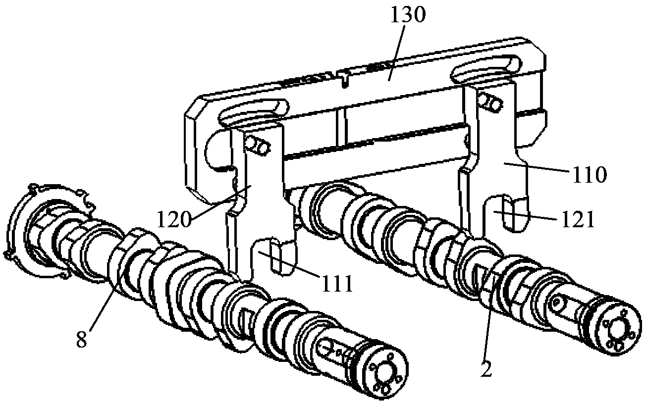
[0037] A camshaft locking device, used to lock and fix the intake camshaft and the intake camshaft sprocket at the first installation position, and to lock and fix the exhaust camshaft and the exhaust camshaft The shaft sprocket is locked and fixed at the second installation positio...


PUM


Abstract

The invention provides a positioning and mounting system and a positioning and mounting method used for an engine timing system. The positioning and mounting system comprises a cam shaft locking device and a crankshaft locking device, wherein the cam shaft locking device is used for locking and fixing a gas inlet cam shaft and a gas inlet cam shaft chain wheel on a first mounting position, and locking and fixing a gas outlet cam shaft and a gas outlet cam shaft chain wheel on a second mounting position; the crankshaft locking device is used for locking and fixing a crankshaft and a crankshaft chain wheel on a third position; a timing chain sleeves around the gas inlet cam shaft chain wheel, the gas outlet cam shaft chain wheel and the crankshaft chain wheel; the first mounting position, the second mounting position and the third mounting position are corresponding; a valve is located on a preset position. According to the positioning and mounting system and the positioning and mounting method used for the engine timing system, the cam shaft locking device, the crankshaft locking device and a chain adjusting device are mutually matched, and the aim of improving the timing assembly precision of an engine is reached.

Description

technical field [0001] The invention relates to the technical field of engines, in particular to a positioning installation system and a positioning installation method for an engine timing system. Background technique [0002] The timing system is an important part of the engine gas distribution system. Generally, the crankshaft drives the camshaft on the engine cylinder head through the timing belt or the timing chain, and then the camshaft drives the tappet, which is located directly above the valve, so that The valve reciprocates up and down to realize the opening and closing of the valve. Therefore, the timing system needs to be connected with the crankshaft and cooperate with a certain transmission ratio to ensure the accuracy of the intake and exhaust time, that is, the valve opens and closes at the correct time. If the timing is wrong, it may cause the piston top valve phenomenon. [0003] In order to make the rotational angle positions of the engine camshaft and t...

Claims


Application Information

Patent Timeline
Patent Type & Authority Applications(China)
IPC IPC(8): B25B11/02B25B27/22
CPCB25B11/02B25B27/22
Inventor 梁呈兴秦颖张艳青贺燕铭马童立李红强周启顺
Owner 北京汽车动力总成有限公司
Learn More