Polycrystalline ingot furnace

A technology of polycrystalline ingot casting and furnace body, which is applied in the direction of polycrystalline material growth, single crystal growth, crystal growth, etc., can solve problems such as uneven heat dissipation, dislocation formation, and affecting the quality of polycrystalline silicon, so as to promote uniform crystal growth, Effect of improving ingot quality

Inactive Publication Date: 2014-12-31
ZHEJIANG GUIHONG ELECTRONICS TECH
View PDF3 Cites 0 Cited by
  • Summary
  • Abstract
  • Description
  • Claims
  • Application Information

AI Technical Summary

Problems solved by technology

[0002] At present, in the polycrystalline ingot furnace that uses the semi-melting process to produce silicon ingots, a square and flat plate-shaped heat exchange block is installed at the bottom of the crucible in the furnace. During the process, convex crystal planes will appear, dislocations will be formed, and impurities will be deposited, which will affect the quality of polysilicon, and the yield of the polysilicon produced is only about 64%, and the four corners can easily melt the silicon material that should remain unmelted. Therefore, the effect of producing the whole ingot cannot be achieved

Method used


Image

  • Polycrystalline ingot furnace
  • Polycrystalline ingot furnace

Examples


Embodiment Construction

[0009] The present invention will be described in detail below in conjunction with the accompanying drawings.

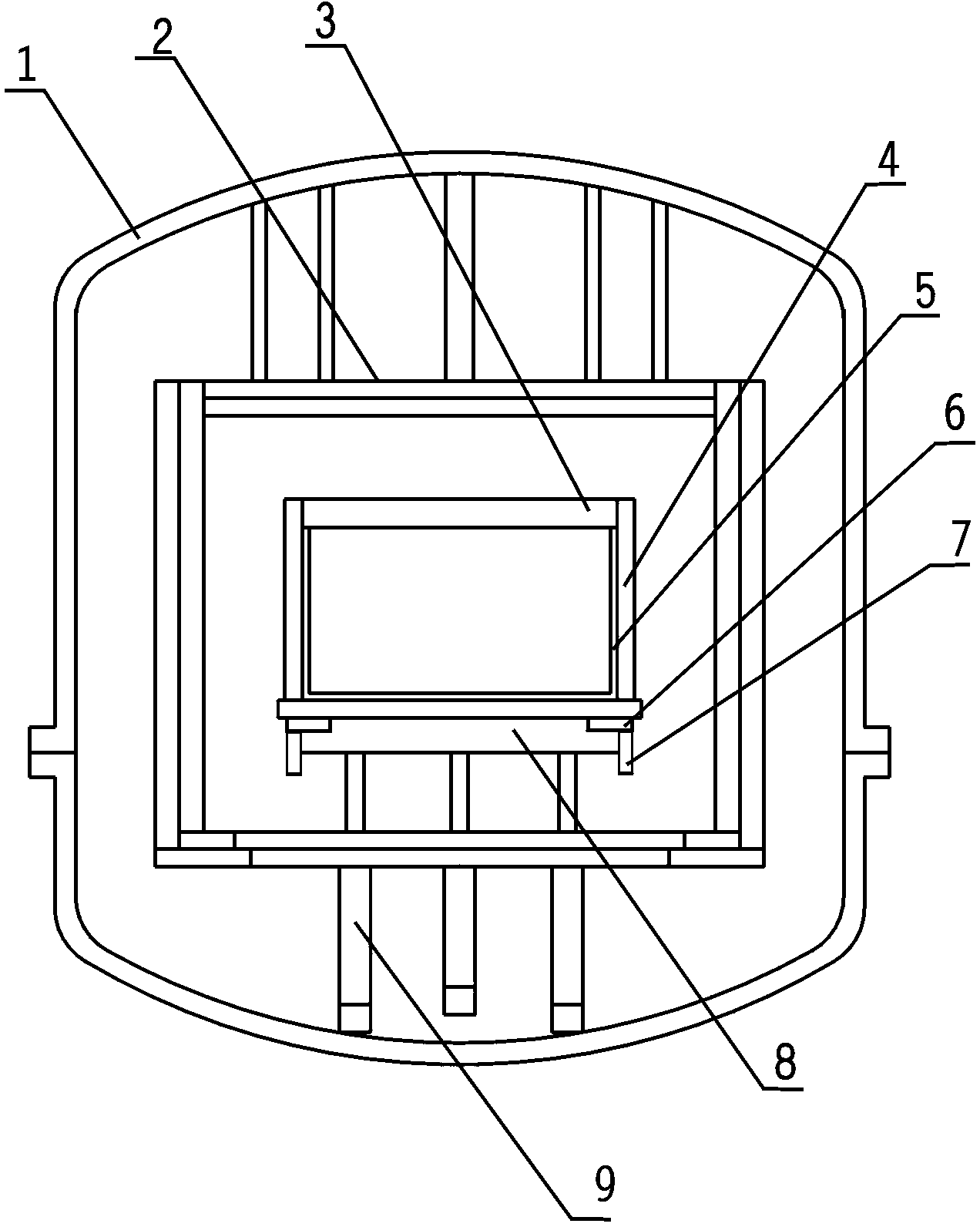
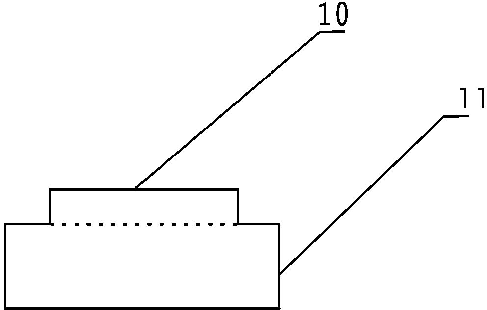
[0010] refer to figure 1 and figure 2 In the furnace body 1 of the polycrystalline ingot casting furnace, a heat insulating cage 2 is erected through a pillar 9, a crucible 5 is located in the heat insulating cage 2, a top heater 3 is arranged on the top of the crucible 5 and in the heat insulating cage 2, and Side heaters 4 are provided on both sides of the crucible 5 and in the heat insulation cage 2, and a convex heat exchange block 8 is provided at the bottom of the crucible 5, and the raised portion 10 is in contact with the bottom of the crucible 5. Heat insulation strips 6 are provided around the raised portion 10 of the upper part of the heat exchange block 8, and thermal insulation blankets 7 are provided around the flat plate part 11 of the lower part of the heat exchange block 8, and the thermal insulation blanket 7 exceeds at least the flat plate part 1...


PUM


Abstract

The invention relates to a polycrystalline ingot furnace. A crucible of the polycrystalline ingot furnace is positioned in a heat insulation cage, a top heater is arranged at the top of the crucible and in the heat insulation cage, and side heaters are arranged on the two sides of the crucible and in the heat insulation cage. A heat exchange block is arranged at the bottom of the crucible and is convex, and the convex surface of the heat exchange block is in contact with the bottom of the crucible. Heat insulation strips are arranged on the periphery of the upper convex part of the heat exchange block, and insulating felt is arranged on the periphery of the lower flat plate part of the heat exchange block and at least exceeds the bottom of the flat plate part of the heat exchange block more than 10 cm. According to the polycrystalline ingot furnace, as the heat exchange block is thick in the middle and thick in two sides, the heat insulation strips enable heat to dissipate to the two sides from the middle (namely, the convex part) slowly. The insulating felt exceeds the lower part of the heat exchange block, so that the bottom of the heat exchange block has an enough large longitudinal temperature gradient, and heat can uniformly radiate out from the lower surface of the heat exchange block. Uniform crystal growth is promoted, the quality of ingot casting is improved, and enough infusible silicon materials can be fully retained in a furnace body to facilitate next ingot casting.

Description

technical field [0001] The invention relates to a polycrystalline ingot casting furnace. Background technique [0002] At present, in the polycrystalline ingot furnace that uses the semi-melting process to produce silicon ingots, a square and flat plate-shaped heat exchange block is installed at the bottom of the crucible in the furnace. During the process, convex crystal planes will appear, dislocations will be formed, and impurities will be deposited, which will affect the quality of polysilicon, and the yield of the polysilicon produced is only about 64%, and the four corners can easily melt the silicon material that should remain unmelted. Therefore, the effect of producing the whole ingot cannot be achieved. Contents of the invention [0003] The object of the present invention is to provide a polycrystalline ingot casting furnace which can prevent convex crystal planes from appearing in the crystal growth process and can produce relatively complete silicon ingots. ...

Claims


Application Information

Patent Timeline
Patent Type & Authority Applications(China)
IPC IPC(8): C30B29/06C30B28/06
Inventor 王土军徐闻韬徐增宏
Owner ZHEJIANG GUIHONG ELECTRONICS TECH
Why Eureka
Try Eureka