Pressure-bearing type glass heat pipe solar heat collector runner and heat collector
A technology of solar collectors and glass heat pipes, applied to solar collectors, solar collectors using working fluids, solar thermal energy, etc., to achieve the effects of increased heat transfer rate and pressure bearing capacity
- Summary
- Abstract
- Description
- Claims
- Application Information
AI Technical Summary
Problems solved by technology
Method used
Image

Examples
Embodiment 1
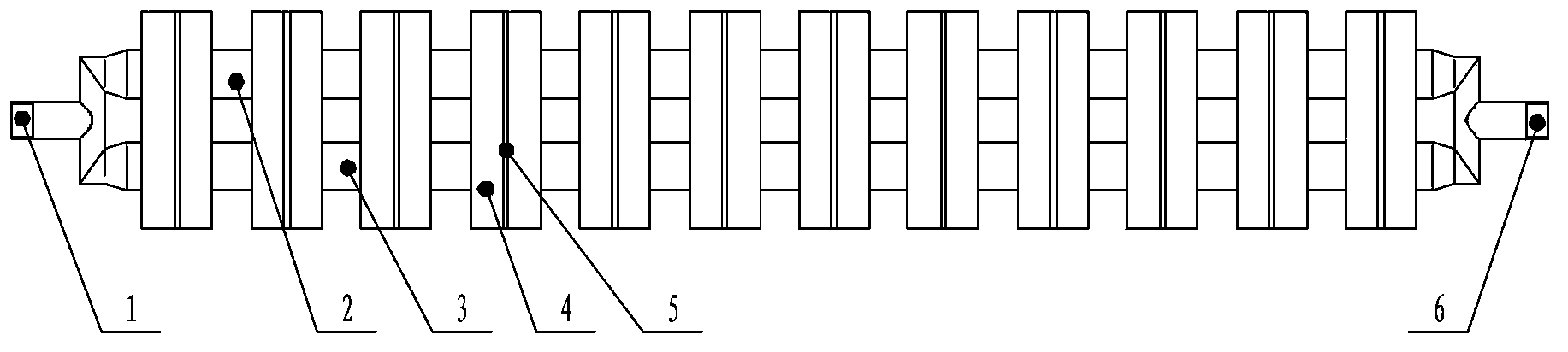
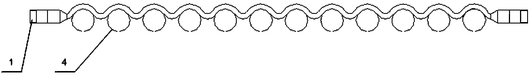
[0028] Such as figure 1 , figure 2 The flow path of the pressure-bearing glass heat pipe solar heat collector shown includes the inlet water nozzle 1, the first branch flow channel 2, the second branch flow channel 3 and the outlet water nozzle 6 connected in sequence; the two branch flow channels are wave Shaped metal flow channel, the inner side of the crest is in close contact with the outer side of a heat conduction ring 4; the heat conduction ring 4 is provided with a narrow gap 5. The condensing end of the glass heat pipe is inserted into the heat conduction ring 4 and tightly fitted with the inner side of the heat conduction ring.
[0029] The working process of this embodiment is: the glass heat pipe transfers the heat converted from solar energy to the heat conduction ring 4, and the heat conduction ring 4 transfers the heat to the first branch channel 2 and the second branch channel 3, and the inlet water The fluid entering the wave-shaped flow channel through the...
Embodiment 2
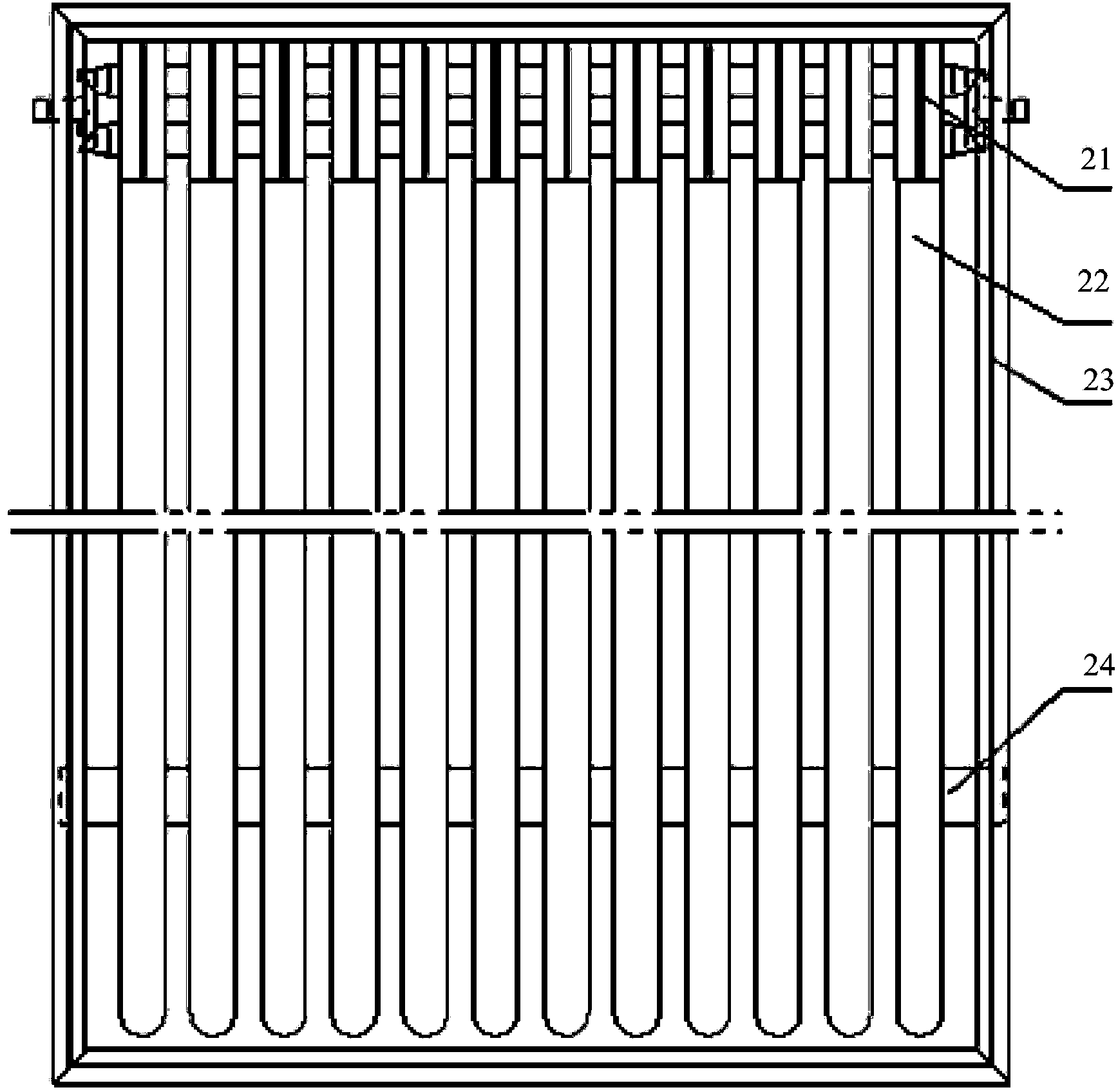
[0041] Such as image 3 , Figure 4 A pressure-bearing glass heat pipe solar collector shown includes the aforementioned heat collector flow channel 21, glass heat pipe 22, frame 23, horizontal frame 24, glass cover plate 25, insulation layer 26, back plate 27 and composite Parabolic condenser 28.
[0042] The glass cover plate 25 and the back plate 27 are connected through the frame 23 to form the inner space of the heat collector.
[0043] The outer surface of the evaporation end of the glass heat pipe 22 is coated with a selective absorption coating with strong weather resistance. The condensing end of the glass heat pipe 22 is inserted into the heat conduction ring of the flow channel 21 of the heat collector to form a heat absorber of the heat collector.
[0044] The compound parabolic concentrating mirror 28 is located above the thermal insulation layer 26 and below the glass heat pipe 22, and the three are sequentially fixed in the inner space of the heat collector t...
PUM
 Abstract
Description
Claims
Application Information
 - Generate Ideas
- Intellectual Property
- Life Sciences
- Materials
- Tech Scout
- Unparalleled Data Quality
- Higher Quality Content
- 60% Fewer Hallucinations
Browse by: Latest US Patents, China's latest patents, Technical Efficacy Thesaurus, Application Domain, Technology Topic, Popular Technical Reports.
© 2025 PatSnap. All rights reserved.Legal|Privacy policy|Modern Slavery Act Transparency Statement|Sitemap|About US| Contact US: help@patsnap.com