
Preparation method of optic fiber sensing ring capable of releasing internal winding stress force

A technology of sensing rings and fiber optic rings, which is applied in the field of fiber optic gyroscopes, can solve problems such as gyroscope output instability, optical fiber optical performance index decline, and damage to ring stability, so as to eliminate influences, improve temperature performance, and reduce heat dissipation. The effect of stress

Active Publication Date: 2014-12-31
BEIJING AUTOMATION CONTROL EQUIP INST
View PDF4 Cites 12 Cited by
  • Summary
  • Abstract
  • Description
  • Claims
  • Application Information

AI Technical Summary

Problems solved by technology

The optical fiber is wound on the surface of the skeleton under a certain tension. After the ring is cured, the tension cannot be eliminated in the optical fiber, and the optical performance of the optical fiber decreases. Especially when the ring is in a temperature-changing environment, the tension changes with the temperature. As a result, the output of the entire gyro is unstable, and due to the cylindrical characteristics of the skeleton material, the cylindrical winding surface will be completely stretched in the radial direction due to the influence of temperature, which will exert additional stress on the optical fiber wound on it, further destroying the stability of the ring, making it difficult to meet the requirements of the optical fiber. Gyro Temperature Performance Requirements

Method used


Image

  • Preparation method of optic fiber sensing ring capable of releasing internal winding stress force
  • Preparation method of optic fiber sensing ring capable of releasing internal winding stress force
  • Preparation method of optic fiber sensing ring capable of releasing internal winding stress force

Examples


Embodiment Construction

[0023] The preparation method of the optical fiber sensing loop capable of releasing internal winding stress of the present invention will be described in detail below in conjunction with the accompanying drawings and embodiments.

[0024] A method for preparing an optical fiber sensing loop capable of releasing internal winding stress, comprising the following steps:

[0025] step 1

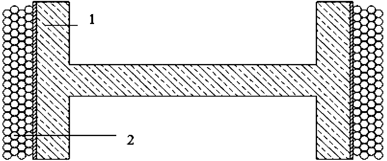
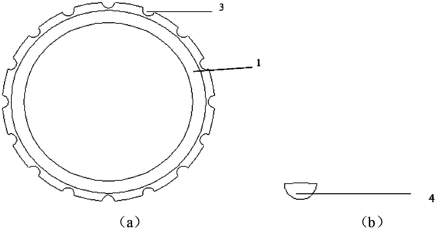
[0026] The ring frame 1 is cleaned with an organic solvent to remove attachments and pollutants on the winding surface; the semi-cylindrical body 4 is filled in the groove 3 of the ring frame 1 .

[0027] step 2

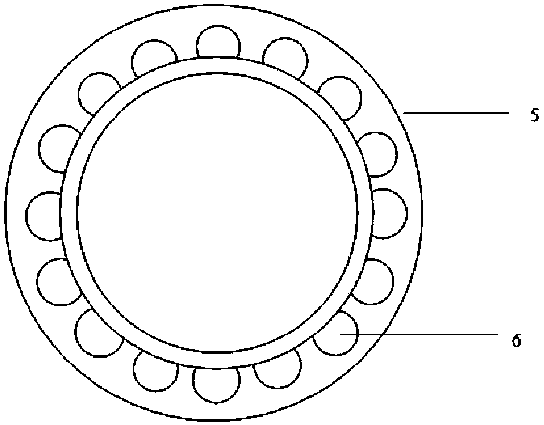
[0028] Fix the hoop frame 1 with two winding tooling 5, wherein the opening 6 of the winding tooling 5 is installed in a staggered manner with the groove 3 of the hoop frame 1, so as to prevent the half cylinder 4 filled in the groove 3 from slipping out.

[0029] step 3

[0030] Put the polarization-maintaining optical fiber 2 and the ring frame 1 into a high-temperature test box a...


PUM


Abstract

The present invention belongs to the technical field of optic fiber gyroscopes, and in particular relates to a preparation method of an optic fiber sensing ring capable of releasing internal winding stress force. The method comprises: filling a half cylinder into the concave groove on the outer circumference of the ring skeleton; adopting winding tool equipment to fix the ring skeleton, wherein the hole opening portion of the winding tool equipment and the concave groove of the ring skeleton are arranged in a staggered form; carrying out a dehumidifying treatment on the polarization maintaining optical fiber and the ring skeleton; adopting a quadrupole symmetry method to closely wind the polarization maintaining optical fiber on the ring skeleton in a side-by-side manner so as to form the optic fiber ring; curing the optic fiber ring, and under the semi-solidification state, pulling out the half cylinder; carrying out secondary curing on the optic fiber ring; and disassembling the winding tool equipment to complete the production of the optic fiber sensing ring. According to the present invention, the adverse effects of the winding stress force on the gyroscope performance are eliminated, and the work stability and the precision of the gyroscope under the temperature change environment are improved.

Description

technical field [0001] The invention belongs to the technical field of optical fiber gyroscopes, and in particular relates to a method for preparing an optical fiber sensing ring capable of releasing internal winding stress. Background technique [0002] The fiber optic sensing ring is the core component of the fiber optic gyroscope that uses the Sagnac mechanism to work and is sensitive to the increment of the rotation angle. Since the fiber itself is a very sensitive sensor, it is extremely sensitive to factors such as temperature, magnetic field, and stress. , so the optical fiber sensing loop is inevitably affected by these factors. For a long time, temperature performance has been an important index in the research and engineering application of FOG. The ambient temperature will directly and indirectly induce additional phase error, which is indistinguishable from the phase difference introduced by rotation, resulting in the zero error of FOG. [0003] At present, the ...

Claims


Application Information

Patent Timeline
IPC IPC(8): G01C25/00
CPCG01C25/00
Inventor 毕聪志吴衍记徐广海孙国飞张丽哲
Owner BEIJING AUTOMATION CONTROL EQUIP INST
Learn More