Check patentability & draft patents in minutes with Patsnap Eureka AI!

Partially colored optical element and method of manufacturing the same

A technology of optical components and parts, applied in the direction of optical components, optical components, optics, etc., can solve the problems of reducing safety advantages, and achieve the effects of saving coating procedures, avoiding error sources, and smooth transitions

Inactive Publication Date: 2019-11-05
ROBERT BOSCH GMBH
View PDF6 Cites 0 Cited by
  • Summary
  • Abstract
  • Description
  • Claims
  • Application Information

AI Technical Summary

Problems solved by technology

However, this combiner has the disadvantage that it illuminates only a small amount of light (eg brake lights) of vehicles approaching ahead and thus reduces the safety advantages of the system

Method used


Image

  • Partially colored optical element and method of manufacturing the same
  • Partially colored optical element and method of manufacturing the same
  • Partially colored optical element and method of manufacturing the same

Examples


Embodiment Construction

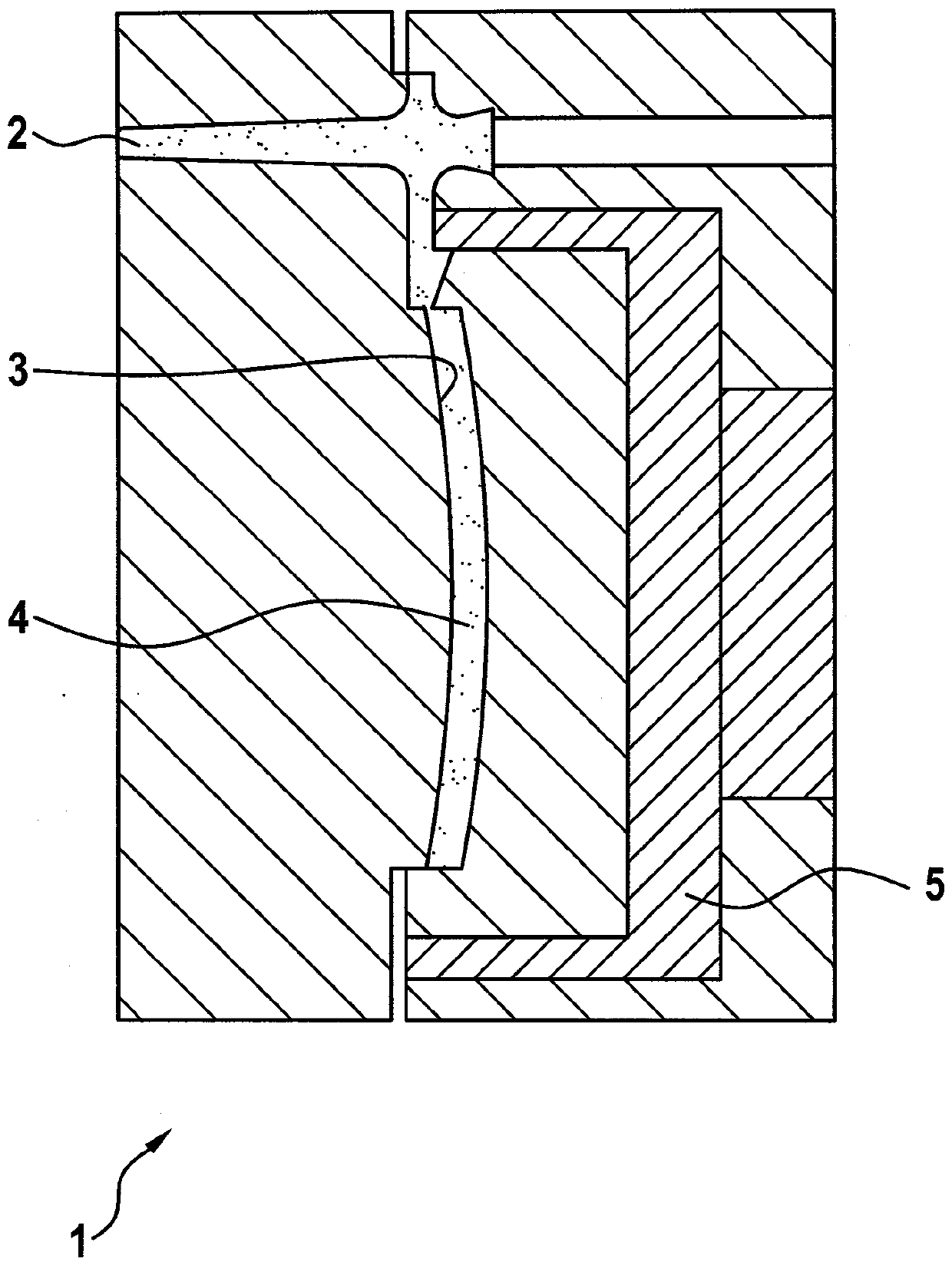
[0030] In order to produce an optical element according to the invention, such as a partially colored plastic combiner tray, it is possible, for example, to use a die-casting machine with an injection stamping tool and an adjustable press with a die-casting tool with a paint metering device . exist figure 1 In a first step shown in , a transparent molded body is produced in a known manner on the die-casting machine from, for example, the thermoplastic polycarbonate (PC) with a tool 1 , for example an injection stamping tool. In this case, the cavity 3 is first filled with a liquid plastic melt through the spout 2 of the tool 1 and the first layer 4 is then pressure-regulated formed by means of a stamping punch 5 . The stamping punch 5 can be designed, for example, in such a way that it has a stamping edge at the cut-out or sprue and in this way separates the sprue with a stamping stroke. If the first layer 4 requires an incision thicker than the stamping stroke, the molded b...


PUM


Abstract

The invention relates to anoptical element 30, comprising a molding body 31 which is diaphanous at least on a part. The molding body is provided with at least a first layer 32 made of a first light-admitting plastic. Thefirst layer 32 is at least connected with a second layer 33 made of a second plastic in a part region. The light-admitting quality of the second plastic is poorer than that of the first plastic. The second layer 33 is provided with at least two positions with different thicknesses. The invention also relates to a method for manufacturingthe optical element 30.

Description

technical field [0001] The invention relates to an optical element comprising an at least partially light-transmissive molded body having at least one first layer of a first light-transmissive plastic. The invention also relates to a method for producing said optical element. Background technique [0002] In many optical systems, transparent plastic surfaces (so-called "Combiners") are used mainly in Head-Up Display (HUD) systems to display important driving information to the driver of the vehicle in the direct viewing area, Examples include speed, navigation cues or hazard signs. For this purpose, a virtual image is created in front of the windshield, so that the driver of the vehicle can simultaneously perceive the surrounding environment and driving information without having to refocus the eyes. The virtual image can be generated on the one hand directly through the windshield or on the other hand on a combiner in front of the windshield in the field of vision of the ...

Claims


Application Information

Patent Timeline
Patent Type & Authority Patents(China)
IPC IPC(8): G02B27/01G02B5/00B29D11/00B29C45/16
CPCB29C33/40B29C45/0046B29C45/16B29C45/1635B29C45/1679B29C45/37B29C45/56B29C2045/1682B29C2791/006B29D11/0073B29K2021/003B29K2021/006B29K2075/00B29K2827/18B29K2995/002B29K2995/0026B29L2031/3475G02B27/01G02B2027/0118G02B2027/0194
Inventor S.阿佩尔特S.盖泽
Owner ROBERT BOSCH GMBH
Features
  • R&D
  • Intellectual Property
  • Life Sciences
  • Materials
  • Tech Scout
  • Unparalleled Data Quality
  • Higher Quality Content
  • 60% Fewer Hallucinations
Learn More