Parallel tri-wire welding system and method

A welding system and welding method technology, applied in welding equipment, arc welding equipment, manufacturing tools, etc., can solve the problems of insufficient filler wire melting, welding defects, insufficient energy, etc., and achieve good accessibility, low cost, Easy-to-use effects

Pending Publication Date: 2019-08-16
AOTAI ELECTRIC
View PDF0 Cites 8 Cited by
  • Summary
  • Abstract
  • Description
  • Claims
  • Application Information

AI Technical Summary

Problems solved by technology

However, the filler wire is actually filled in as a cold wire, relying on the energy of the double open arc and the heat of the molten pool to melt, so when the welding parameters are small, it is easy to have insufficient energy, insufficient melting of the filler wire, and welding defects.

Method used


Image

  • Parallel tri-wire welding system and method
  • Parallel tri-wire welding system and method
  • Parallel tri-wire welding system and method

Examples


Embodiment 1

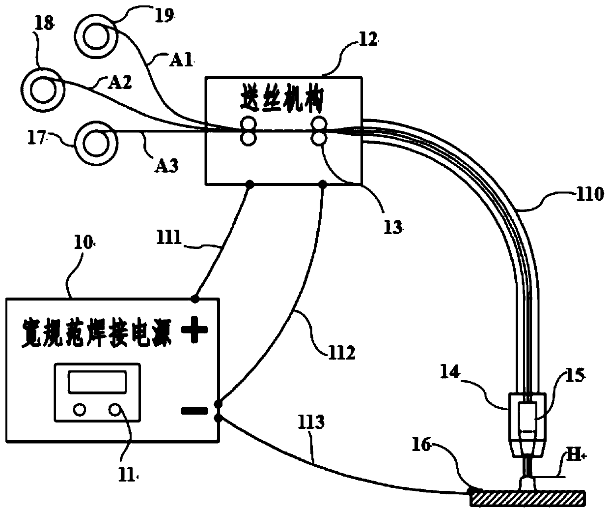
[0047] In one or more embodiments, a parallel three-wire welding system is disclosed, see figure 1, mainly includes: a wide specification welding power supply 10 and a control system 11 for controlling the output of the welding power supply, a wire feeding mechanism 12 with a three-slot wire feed wheel 13, a conventional welding torch 14 with a three-hole contact tip assembly 15 and welding Base material 16. The welding power supply 10 is connected to the wire feeding mechanism through the wire feeding machine control cable 111, and the wire feeding mechanism is connected to the welding torch through the wire feeding tube, and the welding torch passes through one pole of the output electrode of the wide specification welding power supply. The welding cable 110 attached with the shielding gas hose is connected, and the other pole of the output electrode of the wide specification welding power supply is connected to the base metal 16 to be welded through the base metal cable 113...

Embodiment 2

[0070] In one or more embodiments, a method of parallel three-wire welding is provided, comprising:

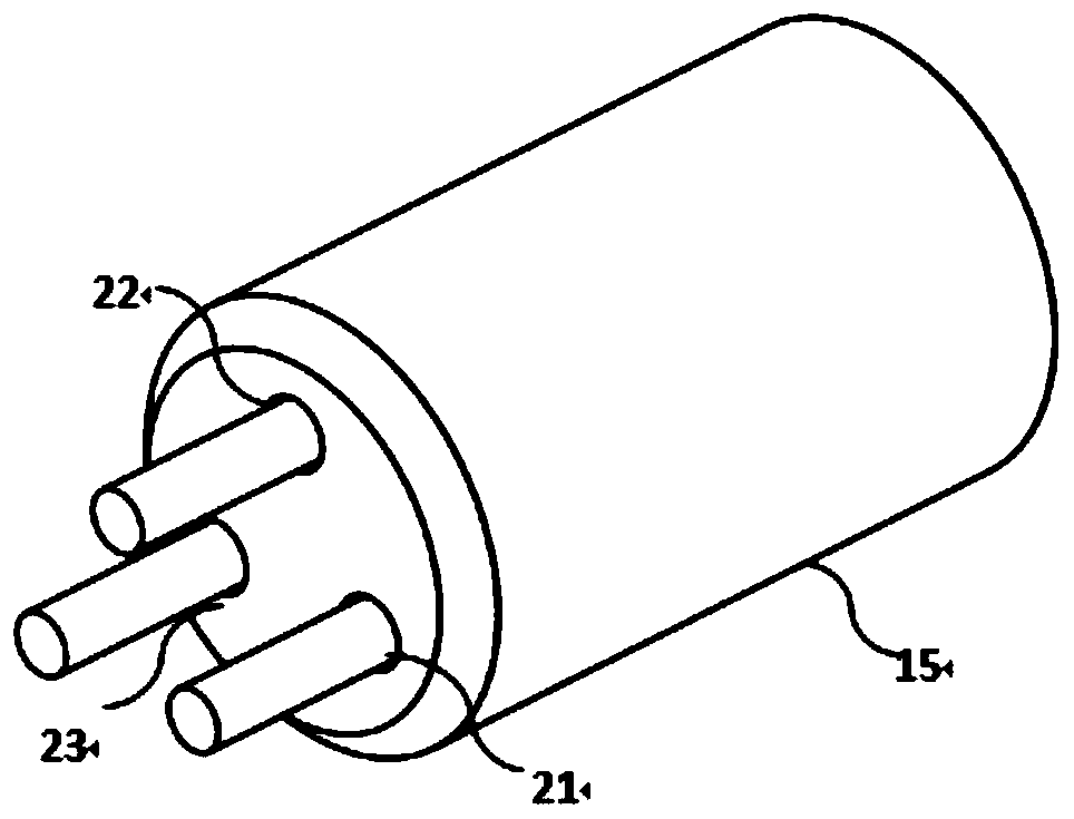
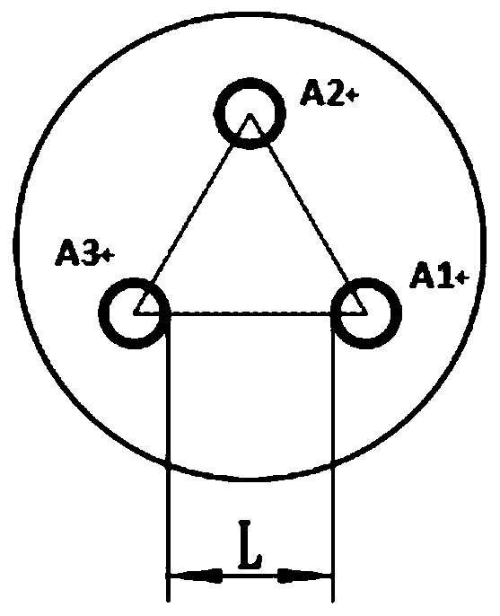
[0071]The output current waveform is provided to the contact tip through a wide range welding power supply; wherein the contact tip includes a first outlet hole, a second outlet hole and a third outlet hole; the first outlet hole, the second outlet hole and the third outlet hole are separated from each other, And the projection points of the centers of the first outlet hole, the second outlet hole and the third outlet hole on the surface of the workpiece are three vertices of an equilateral triangle, so that the distance between the three welding wires is L;

[0072] The wire feeding mechanism provides the first welding wire to the contact tip, and the first welding wire is delivered through the first outlet hole;

[0073] The wire feeding mechanism provides the second welding wire to the contact tip, and the second welding wire is delivered through the second outlet hole;

...


PUM


Abstract

The invention discloses a parallel tri-wire welding system and method. The welding system comprises a wide-range welding power supply, a wire conveying mechanism with a tri-slot wire conveying wheel and a welding gun with a tri-hole conductive nozzle, wherein three welding wires are simultaneously conveyed to the welding gun through the wire conveying mechanism and separately penetrate through three independent holes which are distributed in the conductive nozzle at certain intervals; and welding waveforms output by the welding power supply are supplied to the welding wires through the conductive nozzle, and welding is carried out by simultaneously using the three wires. After the bottom ends of the three wires are molten, molten drops attract each other under electromagnetic action, and the molten drops stably and smoothly flow into a molten bath. The single-power-supply and parallel-tri-wire system has the advantages that the welding efficieny is increased, electric arc shapes and weld penetration size and contours are improved, welding flaws are reduced, and mechanical strength is improved; and at the same time, the three welding wires are stably conveyed by one wire conveying mechanism and go through one conventional welding gun, the operation is convenient, the reaching range of the welding gun is great, and manual, semi-automatic and robot welding demands can be simultaneously met.

Description

technical field [0001] The invention relates to the technical field of welding engineering, in particular to a parallel three-wire welding system and method. Background technique [0002] The statements in this section merely provide background information related to the present invention and do not necessarily constitute prior art. [0003] In recent years, with the continuous development of industrial technology, large structural parts have become more and more widely used in shipbuilding, building bridges, heavy equipment, pressure vessels, rail transit, oil and gas pipelines and other fields. With the variety of products, materials, and service conditions of large structural parts, medium and thick plates with higher strength grades and larger thicknesses are used more and more, and the requirements for welding quality are also getting higher and higher. Therefore, under the premise of ensuring welding quality, improving welding efficiency to meet the needs of modern ma...

Claims


Application Information

Patent Timeline
Patent Type & Authority Applications(China)
IPC IPC(8): B23K9/133
CPCB23K9/1336
Inventor 张光先李朋李志勇晁福田任文建张杰
Owner AOTAI ELECTRIC
Why Eureka
Try Eureka