Power supply without high-voltage electrolysis electrolytic capacitor

A power supply and capacitor technology, which is applied in the direction of instruments, electrical components, and adjustment of electrical variables, etc., can solve problems such as short circuit, poor quality, electrolyte leakage or gushing, and follow the road.

Inactive Publication Date: 2014-12-31
TOP VICTORY INVESTMENTS
View PDF7 Cites 5 Cited by
  • Summary
  • Abstract
  • Description
  • Claims
  • Application Information

AI Technical Summary

Problems solved by technology

In addition, the electrolytic capacitor 13 may be poorly designed or of poor quality, so that the electrolyte will leak or gushes from the capacitor and travel to the circuit area with high voltage, causing short circuit, arcing, causing the electrolyte to catch fire and then trigger electrolysis. Combustible substances other than liquids ignite and burn

Method used


Image

  • Power supply without high-voltage electrolysis electrolytic capacitor
  • Power supply without high-voltage electrolysis electrolytic capacitor
  • Power supply without high-voltage electrolysis electrolytic capacitor

Examples


Embodiment Construction

[0060] In the following description, in order to maintain the consistency of the description of the present invention, in different embodiments, if there are components with the same or similar functions and structures, the same component symbols and names will be used. In addition, in order to clearly present the features of the present invention, some well-known components are omitted in the accompanying drawings.

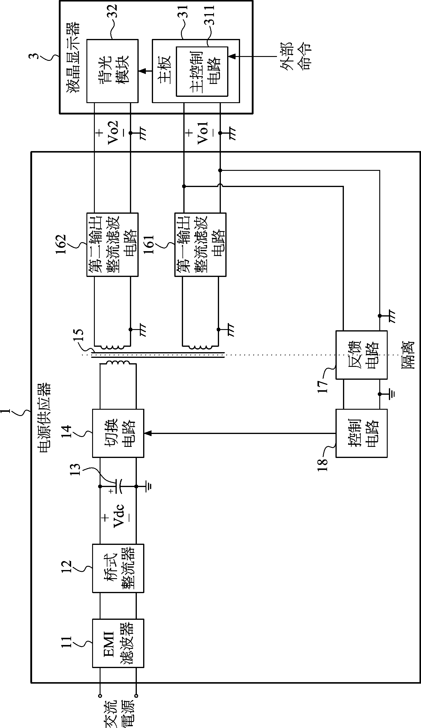
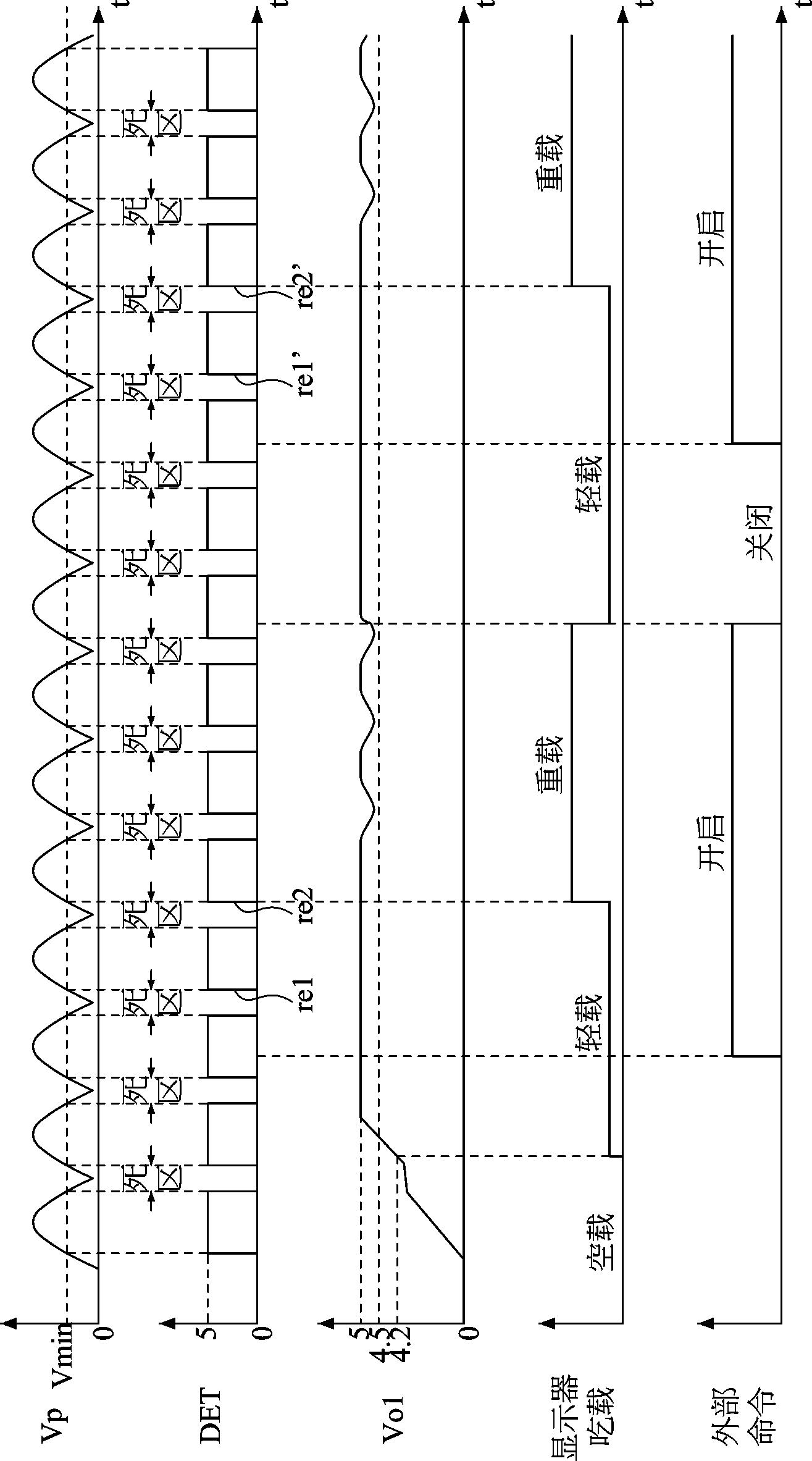
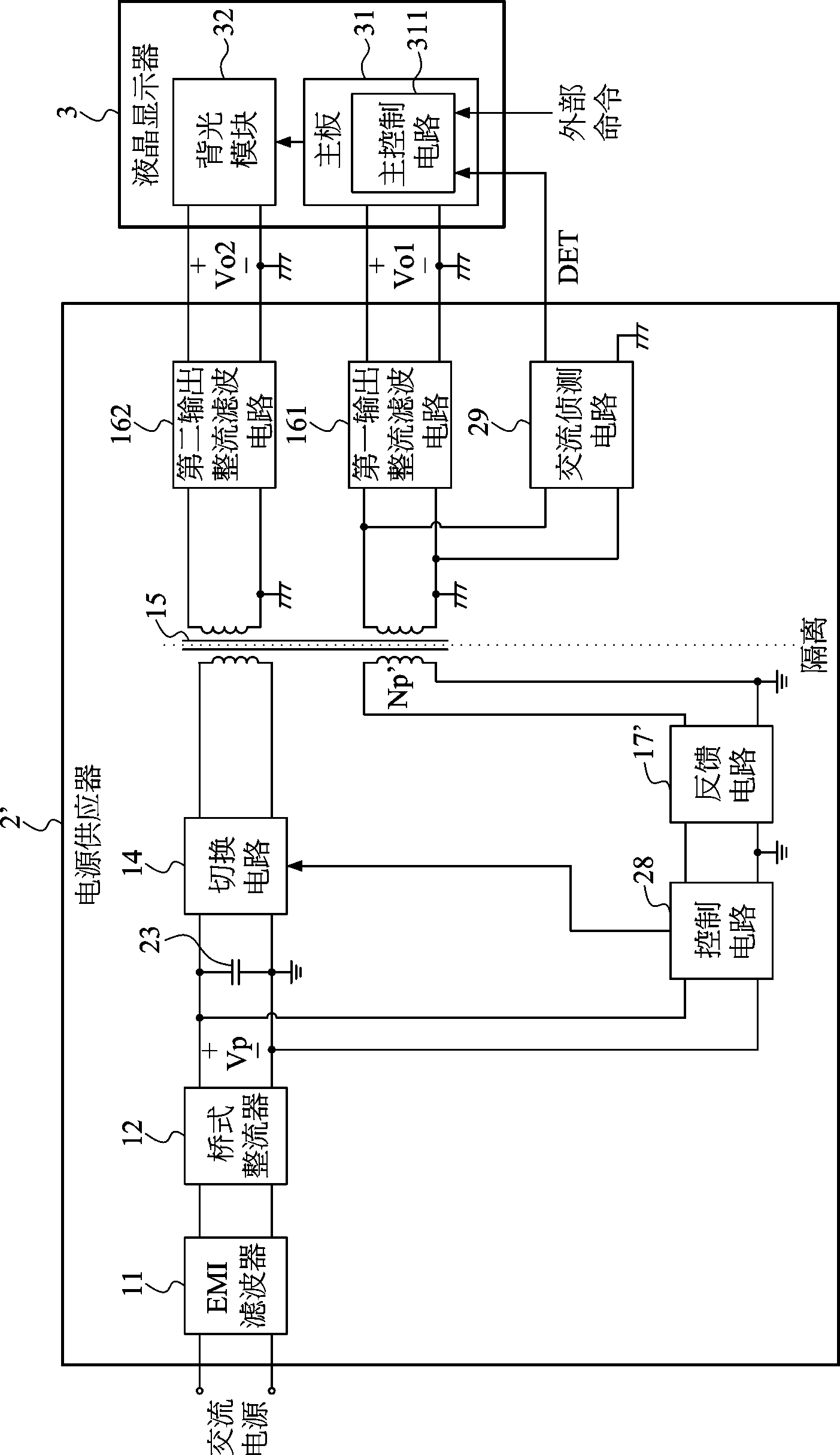
[0061] figure 2 is a circuit block diagram of a power supply according to an embodiment of the present invention, and image 3 for figure 2 A timing diagram of the operation of the power supply and the electronic devices it powers is shown. Please see first figure 2 , the power supply 2 of the present invention is used to supply power to an electronic device. In this embodiment, the electronic device is a liquid crystal display 3 . The power supply 2 of the present invention includes an EMI filter 11, a bridge rectifier 12, a ceramic or film capacitor 23, ...


PUM


Abstract

The invention discloses a power supply which comprises a bridge rectifier, a ceramic or film capacitor, a DC / DC converter and an alternating current detection circuit. The ceramic or film capacitor is adopted by the power supply to replace a conventional common high-voltage electrolytic capacitor on a power input side, so that firing burning is not caused; the cost is lower; and in addition, the power supply can detect two-end voltage of the ceramic or film capacitor, controls the DC / DC converter to stop conversion when the energy of the ceramic or film capacitor is too low, and detects input end voltage of an output rectification filter circuit in the DC / DC converter by the alternating current detection circuit to output a detection signal to inform an electronic device to synergistically receive supply of output voltage output by the output rectification filter circuit. Therefore, light and heavy load changes of the electronic device employing the power supply can be handled.

Description

technical field [0001] The present invention relates to a power supply, and more particularly to a power supply that receives AC power and converts it into a DC output voltage to supply power to an electronic device, wherein the electronic device is, for example, a liquid crystal display. Background technique [0002] figure 1 It is a circuit block diagram of an existing liquid crystal display power supply. See figure 1 , the existing power supply 1 includes an electromagnetic interference (electromagnetic interference, EMI) filter 11, a bridge rectifier 12, an electrolytic capacitor 13, and a direct-current to direct-current (DC / DC) converter, wherein The DC / DC converter includes a switching circuit 14 , a transformer 15 , a first output rectifying and filtering circuit 161 , a second output rectifying and filtering circuit 162 , and a feedback control circuit composed of a feedback circuit 17 and a control circuit 18 . After the AC power is filtered by the EMI filter 11...

Claims


Application Information

Patent Timeline
Patent Type & Authority Applications(China)
IPC IPC(8): H02M3/335H02M1/36H02M1/12
Inventor 高志明陈义雄张志强叶俊宏陈鸿文张书铭江文祥陈俊嘉邱显鸿
Owner TOP VICTORY INVESTMENTS
Why Eureka
Try Eureka