Plain-surface modifying machining Method for tooth surfaces of worm gears

A processing method and tooth surface technology, applied to worm gears, components with teeth, belts/chains/gears, etc., can solve the problems of difficulty in tooth surface modification, inability to visually check the transmission of worm gears and worms, troubles, etc. , to achieve the effects of high processing precision, easy control of the production process, and simple processing process

Active Publication Date: 2015-01-07
ANSTEEL HEAVY MACHINERY CO LTD
View PDF5 Cites 3 Cited by
  • Summary
  • Abstract
  • Description
  • Claims
  • Application Information

AI Technical Summary

Problems solved by technology

It can be seen that, restricted by the structure of the worm gear and worm transmission pair, it is impossible to put the worm gear and the worm into the box at the same time when assembling the worm gear reducer to visually check the transmission situation and make appropriate adjustments. If the transmission fails after assembly, it needs to be disassembled and r

Method used


Image

  • Plain-surface modifying machining Method for tooth surfaces of worm gears
  • Plain-surface modifying machining Method for tooth surfaces of worm gears
  • Plain-surface modifying machining Method for tooth surfaces of worm gears

Examples


Embodiment Construction

[0021] The specific embodiment of the present invention will be further described below in conjunction with accompanying drawing:

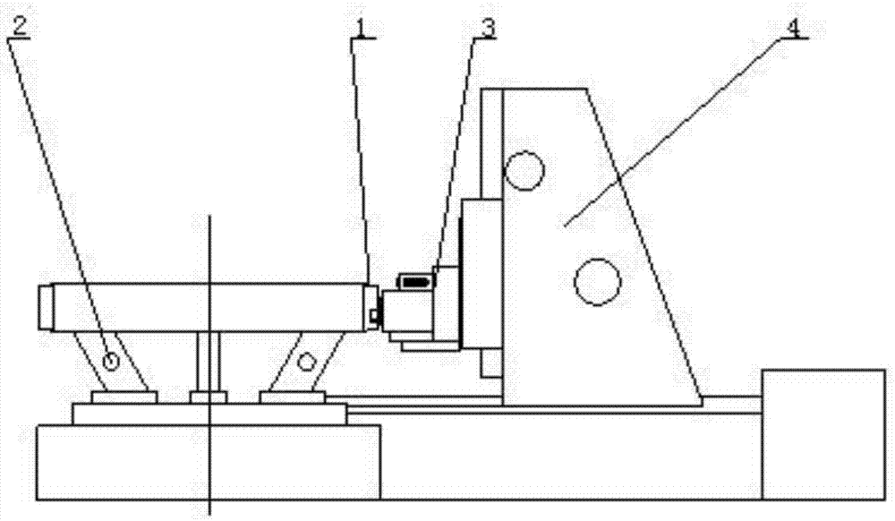
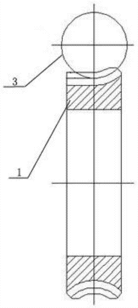
[0022] See figure 1 , is a schematic diagram of the processing state of the present invention, a method for face-to-face modification of the tooth surface of a worm gear according to the present invention, which is used to mill the tooth surface of the 1 / 2 tooth width of the worm gear flat according to the height of the pitch circle, including the following steps

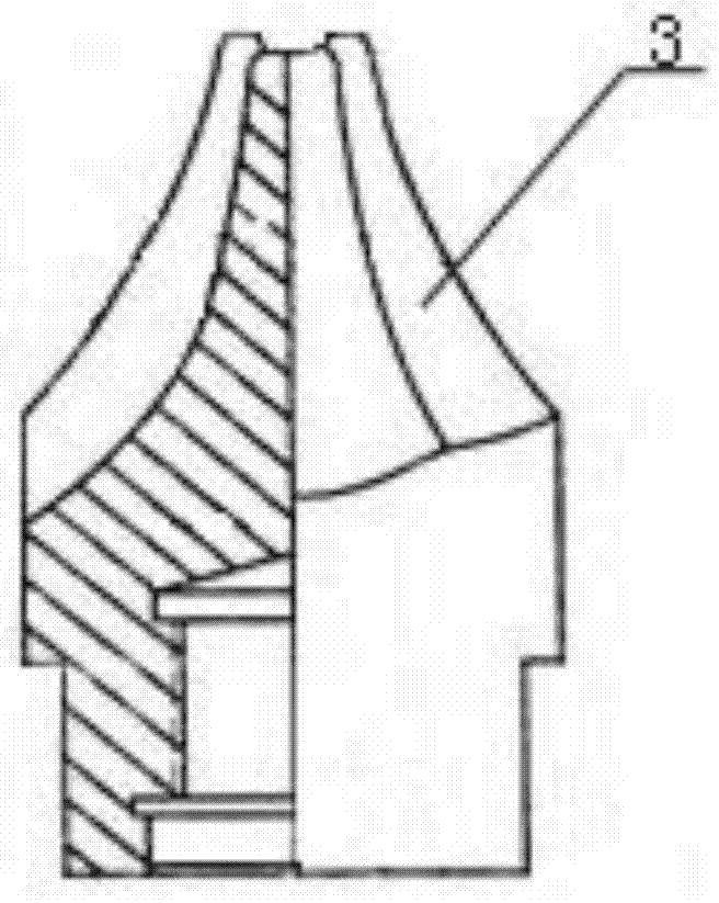
[0023] 1) Process the finger-shaped milling cutter 3 according to the tooth shape at the index circle of the worm wheel after tooth milling, the material of the milling cutter 3 is W18Cr4V, and install the milling cutter 3 on the gear hobbing machine 4;

[0024] 2) Put the milled worm gear workpiece 1 flat on the working table of the gear hobbing machine 4, support it with 8 contour pad irons 2, take the outer circle and end face of the worm gear workpiece 1 as the positioning reference...


PUM


Abstract

The invention relates to a plain-surface modifying machining method for tooth surfaces of worm gears. The plain-surface modifying machining method is used for milling the tooth surfaces in the height directions according to reference circles, and the widths of the tooth surfaces are equal to 1/2 of the tooth widths of the worm gear. The plain-surface modifying machining method includes steps of 1), machining finger-shaped milling cutters according to tooth profiles of the reference circles of the worm gears with milled teeth; 2), laying worm gear workpieces with the milled teeth on worktables of gear bobbing machines and aligning the worm gear workpieces; 3), adjusting the cutters according to the tooth surfaces at the reference circles, and machining the tooth surfaces according to lead angle adjusting differential mechanisms of worms until certain positions of the tooth surfaces are machined; 4), indexing and machining a next tooth surface after each tooth surface is completely machined; 5), machining a plurality of tooth surfaces according to assembly requirements, completely machining the tooth surfaces, coating oil on the tooth surfaces after the tooth surfaces pass inspection, and storing the tooth surfaces. The widths of the certain positions of the reference surfaces are equal to 1/2 of the tooth widths of the worm gears. Compared with the prior art, the plain-surface modifying machining method has the advantages that plain-surface modifying requirements on the tooth surfaces of the worm gears can be met, and the purposes of simultaneously placing the worm gears and the worms into boxes assembling the worm gears and the worms in the boxes can be achieved; machining procedures are simple, production procedures are easy to control, and requirements on the quality of products can be met; indexing functions of the gear bobbing machines can be sufficiently utilized, and accordingly the plain-surface modifying machining method is high in machining precision.

Description

technical field [0001] The invention relates to a tooth surface processing method, in particular to a worm wheel tooth surface straight-face modification processing method. Background technique [0002] Due to the large meshing friction of the worm drive, the difficulty of accurately shoveling the back of the worm gear hob, and the error in shape and size, it is difficult for the machined worm gear tooth surface to completely reach the conjugate state that meets the theoretical requirements with the matching worm tooth surface. When it cannot be adjusted to the best state, it is easy to cause the worm gear transmission to fail. [0003] The assembly process of the worm gear reducer is: fix the bearings at both ends of the worm gear and install the oil seal; put the worm gear into the lower box to adjust the position, cover the upper box and fix it; put the worm into the worm hole, install the worm bearing and the oil seal ; Compress the end cover of the worm wheel and seal ...

Claims


Application Information

Patent Timeline
IPC IPC(8): B23F11/00
Inventor 赵长红陈维赵晓玲高扬
Owner ANSTEEL HEAVY MACHINERY CO LTD
Why Eureka
Try Eureka