Pulley guide rail assembly method and structure and power catwalk of pulley guide rail assembly structure

An assembly method and assembly structure technology, which is applied in the direction of earthwork drilling, drilling pipe, casing, etc., can solve the problems of difficulty in the assembly process of the pulley assembly and the guide rail assembly, the inability to perform assembly operations, and the difficulty of the assembly process. The assembly process is simple and easy, the action process is simple and easy, and the structure is reasonable

Active Publication Date: 2020-08-07
SICHUAN HONGHUA PETROLEUM EQUIP
View PDF7 Cites 0 Cited by
  • Summary
  • Abstract
  • Description
  • Claims
  • Application Information

AI Technical Summary

Problems solved by technology

[0005] In the actual manufacturing process, the assembly process between the trolley assembly and the guide rail assembly is relatively difficult
After in-depth research, the applicant found that since the pulley assembly is usually designed as an integrated structure, and the motor has braking and locking functions, if the motor is not powered on, the pulley cannot walk along the guide rail assembly, and assembly operations cannot be performed at this time
When the motor is energized, the trolley assembly is fed from the end of the guide rail assembly to the guide rail assembly, so that the gear and the rack are meshed. At the same time, the sliding clips of the roller discs on both sides of the bottom of the trolley need to be embedded in the The two sides of the guide rail assembly, which makes the assembly process very difficult

Method used


Image

  • Pulley guide rail assembly method and structure and power catwalk of pulley guide rail assembly structure
  • Pulley guide rail assembly method and structure and power catwalk of pulley guide rail assembly structure
  • Pulley guide rail assembly method and structure and power catwalk of pulley guide rail assembly structure

Examples


Embodiment 1

[0057] Such as Figure 3 to Figure 11 As shown, a method for assembling a pulley guide rail in this embodiment includes the following steps:

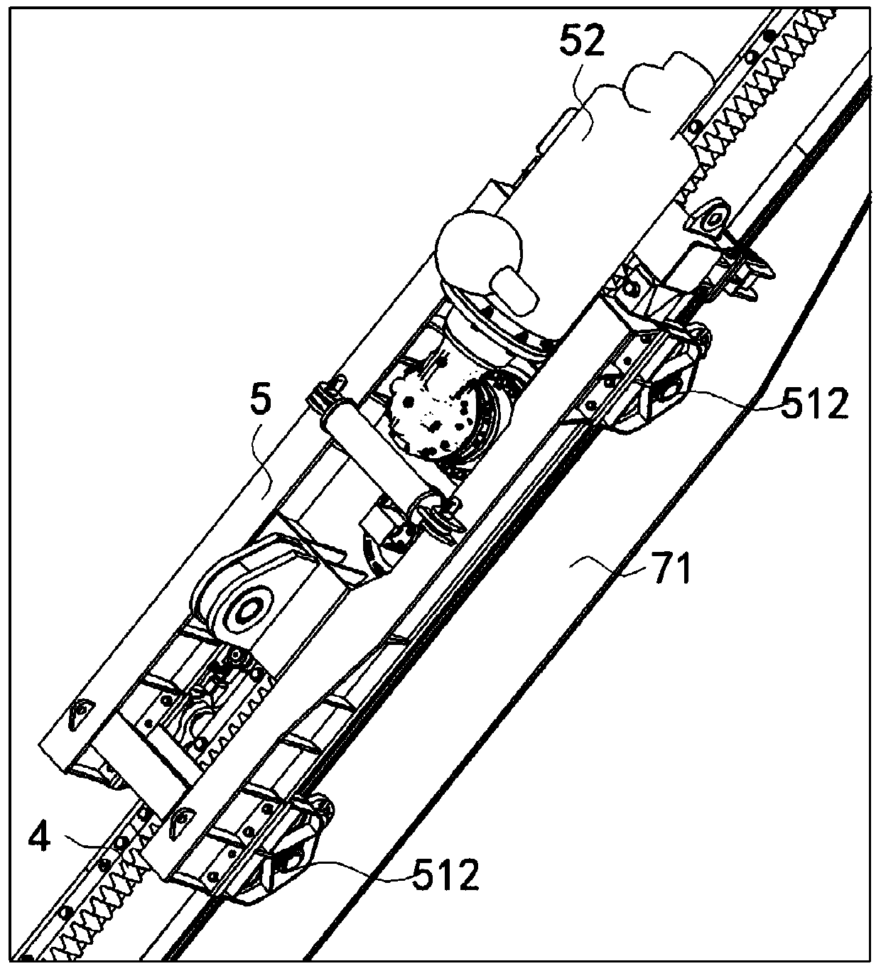
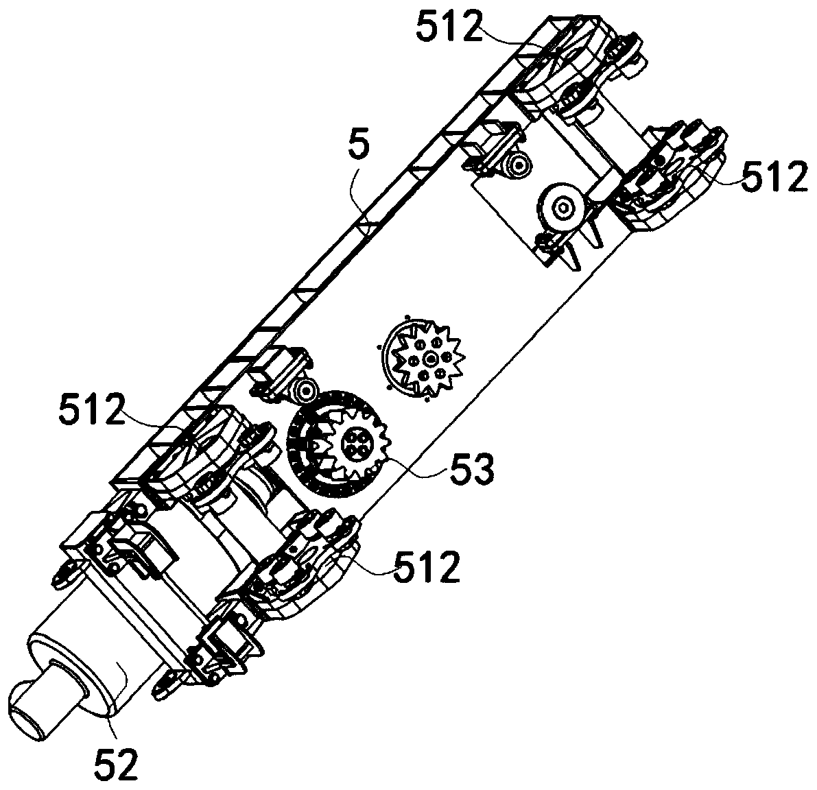
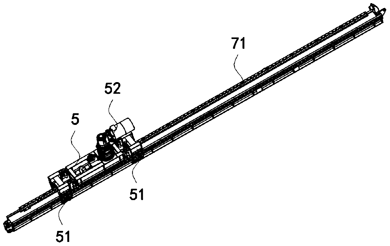
[0058] S1: Place the trolley 5 on the top of the guide rail assembly, and the gear 53 assembled at the bottom of the trolley 5 meshes with the rack 4 on the top of the guide rail assembly;

[0059] S2: Slide the roller disc unit 51 into the two sides of the guide rail assembly;

[0060] S3: On the guide rail assembly, connect the trolley 5 and the roller disc unit 51 through a connecting piece 50 to form an integral structure.

[0061] When adopting the assembling method of the tackle guide rail of the present invention, it is obvious that the tackle assembly at least includes the tackle 5 and the roller disk unit 51, and there is a split structure (mutually independent structure) between the two; for the guide rail assembly, its The two sides can be adapted to the roller disc unit 51, so that the roller disc unit 51 is slidably embed...

Embodiment 2

[0071] like Figure 3 to Figure 11 As shown, a trolley rail assembly structure of this embodiment includes a trolley assembly and a guide rail assembly with a rack 4 on the top, the trolley assembly includes a trolley 5 and a roller disc unit 51, and the trolley 5 and the trolley The roller disc unit 51 can be connected to form an integral structure through the connector 50; wherein,

[0072] The trolley 5 is placed on the top of the guide rail assembly, and the gear 53 assembled at the bottom of the trolley meshes with the rack 4 on the top of the guide rail assembly;

[0073] The roller disc unit 51 is slidably embedded in both sides of the guide rail assembly;

[0074] The trolley 5 placed on the top of the guide rail assembly is connected with the roller disc units 51 embedded in the two sides of the guide rail assembly through the connecting piece 50 to form an integral structure.

[0075] When the trolley guide rail assembly structure of the present invention is adopte...

Embodiment 3

[0081] In order to facilitate the understanding of the present invention, the present invention specifically introduces a specific design of a guide rail assembly through the third embodiment.

[0082] like Figure 9 to Figure 11 As shown, a guide rail assembly of this embodiment includes a guide rail 1 and two guide rails 2; the guide rail 1 includes a web 13 and an upper wing 11 arranged at the upper and lower ends of the web 1 With the lower wing plate 12, the guide rail two 2 includes the web two 23 and the upper wing plate two 21 and the lower wing plate two 22 arranged at the upper and lower ends of the two webs; along the length direction of the guide rail one 1, the two The upper wing plate two 21 of the two guide rails two 2 are respectively connected to the two sides of the upper wing plate one 11 of the guide rail one 1, and the top surface of the upper wing plate one 11 is provided with a rack 4. Guide rail one 1 mainly plays the role of connecting two guide rails...


PUM


Abstract

The invention discloses a pulley guide rail assembly method and structure and a power catwalk of the pulley guide rail assembly structure, and belongs to the technical field of power catwalks. The pulley guide rail assembly method comprises the following steps that S1, a pulley is placed on the top of a guide rail assembly, and a gear assembled at the bottom of the pulley is meshed with a rack atthe top of the guide rail assembly; S2, roller disc units are slidably clamped on both sides of the guide rail assembly; and S3, on the guide rail assembly, the pulley and the roller disc units are connected through connecting parts to form an overall structure. When the pulley guide rail assembly method is adopted, the pulley and the roller disc units are independent of each other, and no mutualrestriction relationship exists between the installation action of the pulley and the installation action of the roller disc units, so that the action process of installing the pulley on the guide rail assembly and the action process of the roller disc units installed on the guide rail assembly are simple and easy, the difficulty of the pulley guide rail assembly process is reduced, the assembly efficiency is improved, and the purpose of assembly is achieved.

Description

technical field [0001] The invention relates to a pulley guide rail assembly method and structure and a power catwalk thereof, belonging to the technical field of power catwalks. Background technique [0002] The power catwalk is a conveying equipment used in the technical field of oil and gas drilling and production equipment. It can transport the drilling tools on the outriggers (legs can also be called bent frames) on both sides of the power catwalk to the drill floor, and can also transport the drilling tools The drilling tools on the table are transported and arranged on the legs on both sides of the power catwalk; such as Chinese patent CN201520866530.4, a power catwalk; Chinese patent CN201420525189.1, a cylinder lifting land power catwalk; Chinese patent CN201420660266.4, a power catwalk for a rack and pinion drilling rig. [0003] The main drive system of the power catwalk is the drive system used to lift the power catwalk cloud beam (the power catwalk cloud beam c...

Claims


Application Information

Patent Timeline
Patent Type & Authority Applications(China)
IPC IPC(8): E21B19/15
CPCE21B19/15
Inventor 李世国田力王尊文吕岩蒋林宏
Owner SICHUAN HONGHUA PETROLEUM EQUIP
Why Eureka
Try Eureka