
Bearing closed-up punch and machining process thereof

A technology of processing technology and punch, which is applied in the field of bearing closing punch and its processing technology, can solve the problems of low processing efficiency, increased manufacturing cost, and non-replaceable die, so as to improve processing efficiency, reduce processing steps, and simple operation Effect

Inactive Publication Date: 2015-01-07
SHENYANG AIRCRAFT CORP
View PDF6 Cites 12 Cited by
  • Summary
  • Abstract
  • Description
  • Claims
  • Application Information

AI Technical Summary

Problems solved by technology

[0002] The existing bearing closing punches have the following deficiencies: 1. The housing and the punching die are of an integrated structure, and the punching die cannot be replaced. When punching bearings of different sizes, the whole punch needs to be replaced, the processing efficiency is low, and the labor intensity of the workers is high. The accumulative error caused by multiple clamping workpieces will easily lead to low yield of bearing closing punch, which will increase the manufacturing cost virtually; 2. During processing, the verticality, parallelism, depth of the groove and the The protruding height of the punching die is not easy to control. In addition, the equal division control of the punching die and the splitting angle of 45° and 15° are usually used for processing. 15 degrees, then turn the small pallet back to 0°, use 45° for the inner hole turning tool to turn the punching die at 45°, because the punching die has height dimensions and the size requirements of the arc R, so it is necessary to set the tool multiple times, and pull the small pallet. Angle, not only the processing efficiency is low, but also seriously affect the precision of the bearing closing punch, and then affect the quality of the bearing

Method used


Image

  • Bearing closed-up punch and machining process thereof
  • Bearing closed-up punch and machining process thereof
  • Bearing closed-up punch and machining process thereof

Examples


Embodiment Construction

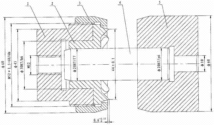
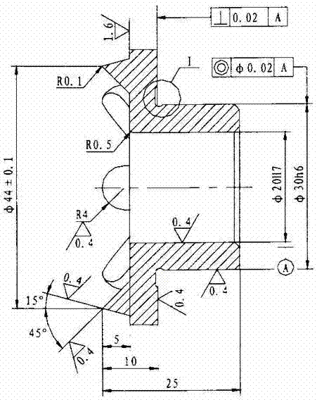
[0040] like figure 1 , figure 2 , image 3 , Figure 6 to Figure 8 As shown, a bearing closing punch includes a housing 1, a die 2, a nut 3, a guide rod 4 and a base 5, wherein the die 2 is located in the groove of the housing 1 and the die 2 and the housing 1 are connected by a screw The cap 3 is assembled and connected into one body, the inner hole of the die 2 is covered with a guide rod 4, and the guide rod 4 is fixedly connected with the base 5. The bearing closing punch has 8 punching points, and has good positioning and centering.

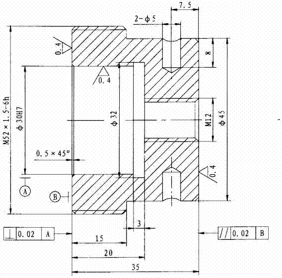
[0041] like figure 2 The processing technology of the shown shell 1 is:

[0042] (1) cutting;

[0043] (2) Turner: first turn the outer circle of shell 1, then flatten the left end face, use the tool setter to align the thread turning tool, finish turning the inner and outer threads to the size requirements, leave the inner hole 0.3-0.5mm, and lengthen the left and right end faces by 0.20- 0.30mm cut off, and control both ends paral...


PUM


Abstract

The invention provides a bearing closed-up punch. The bearing closed-up punch is mainly used for positioning and fixing of a bearing part, a part which requires bearing mounting is clamped between a punch die and a base, an annular ring is punched in a portion of a bearing hole of the part that requires bearing mounting to limit bearing axial and radial movements, the freedom degree of a bearing is limited by means of the bearing closed-up punch, the operation is simple, and the positioning is good; stretching height of the punch can be finely adjusted, the ejecting height can be easily guaranteed, meanwhile, the punch die is in clearance fit with a shell, the punch die is replaceable, and single component production can be performed in case of unqualified sizes; a corresponding machining process is provided according to the structure of the bearing closed-up punch, the machining efficiency of the bearing closed-up punch can be effectively increased, meanwhile, qualities are guaranteed, and the bearing closed-up punch can be accurately and rapidly fixed and positioned; during forming of the punch die, only one-time angle turning of a small supporting plate is required, the forming of the punch die can be finished only by one forming turning tool, machining steps are reduced, and the machining efficiency is increased.

Description

technical field [0001] The invention relates to a bearing closing punch and a processing technology thereof, belonging to the technical field of mechanical processing. Background technique [0002] The existing bearing closing punches have the following deficiencies: 1. The housing and the punching die are of an integrated structure, and the punching die cannot be replaced. When punching bearings of different sizes, the whole punch needs to be replaced, the processing efficiency is low, and the labor intensity of the workers is high. The accumulative error caused by multiple clamping workpieces will easily lead to low yield of bearing closing punch, which will increase the manufacturing cost virtually; 2. During processing, the verticality, parallelism, depth of the groove and the The protruding height of the punching die is not easy to control. In addition, the equal division control of the punching die and the splitting angle of 45° and 15° are usually used for processing....

Claims


Application Information

Patent Timeline
Patent Type & Authority Applications(China)
IPC IPC(8): B23P15/00B23P21/00
CPCB21D37/10B23P15/00B23P15/24
Inventor 赵荣全张建宏王健李晓峰
Owner SHENYANG AIRCRAFT CORP
Learn More