Energy-saving quayside container crane system provided with crossing type double trolleys

A double-trolley, traversing-type technology, applied in the direction of walking bridge cranes, hoisting equipment braking devices, load suspension components, etc., can solve the problems of complicated rope winding, difficult to realize double-trolley structure, complex structure, etc., and achieve winding The rope is simple, the structure is simplified, and the effect of reducing energy consumption

Active Publication Date: 2015-01-07
华电蓝科科技股份有限公司
View PDF11 Cites 3 Cited by
  • Summary
  • Abstract
  • Description
  • Claims
  • Application Information

AI Technical Summary

Problems solved by technology

[0007] For this reason, the technical problem to be solved by the present invention is that the existing quay crane potential energy compensation system

Method used


Image

  • Energy-saving quayside container crane system provided with crossing type double trolleys
  • Energy-saving quayside container crane system provided with crossing type double trolleys
  • Energy-saving quayside container crane system provided with crossing type double trolleys

Examples


Example Embodiment

[0068] Example 1

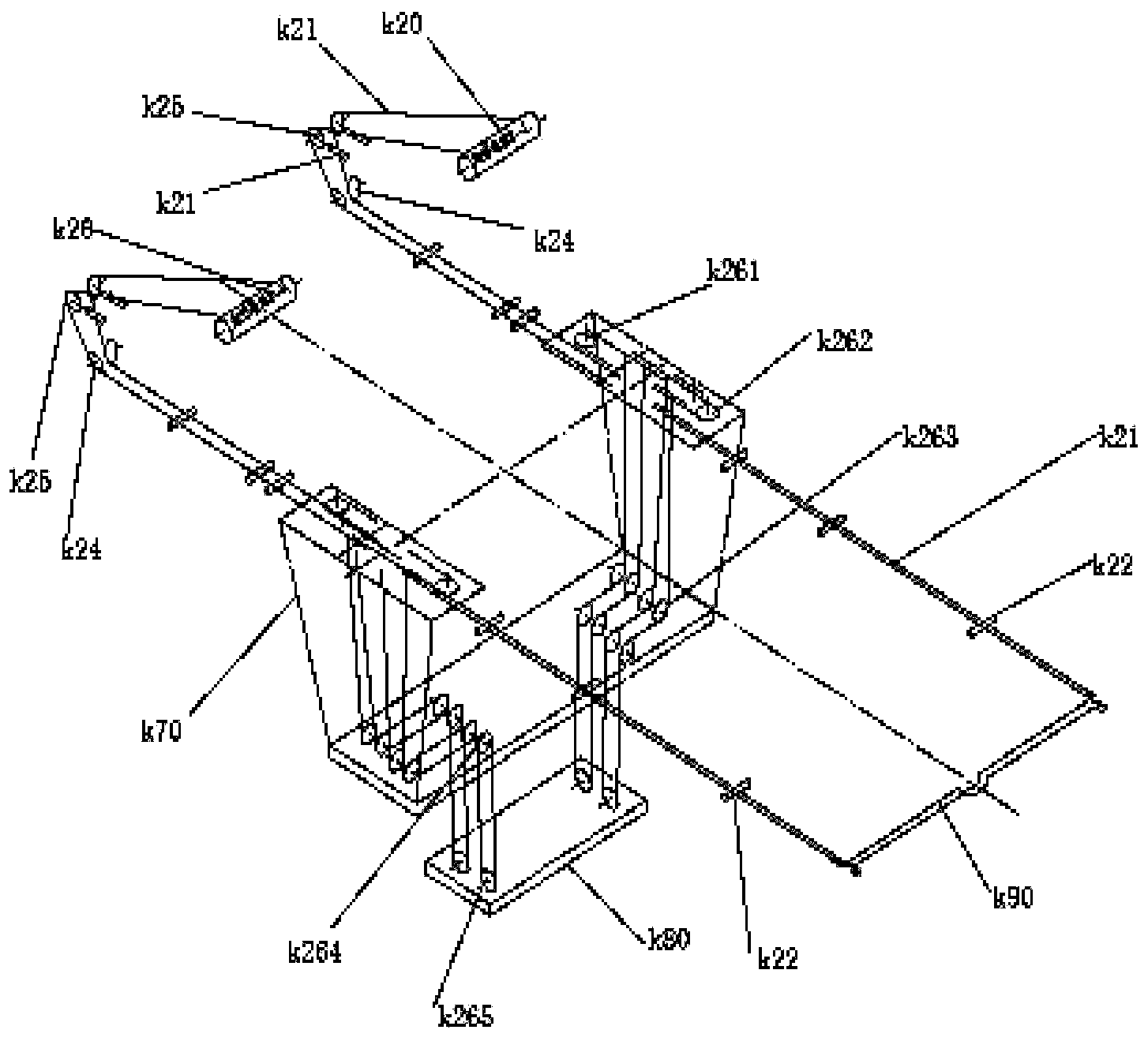
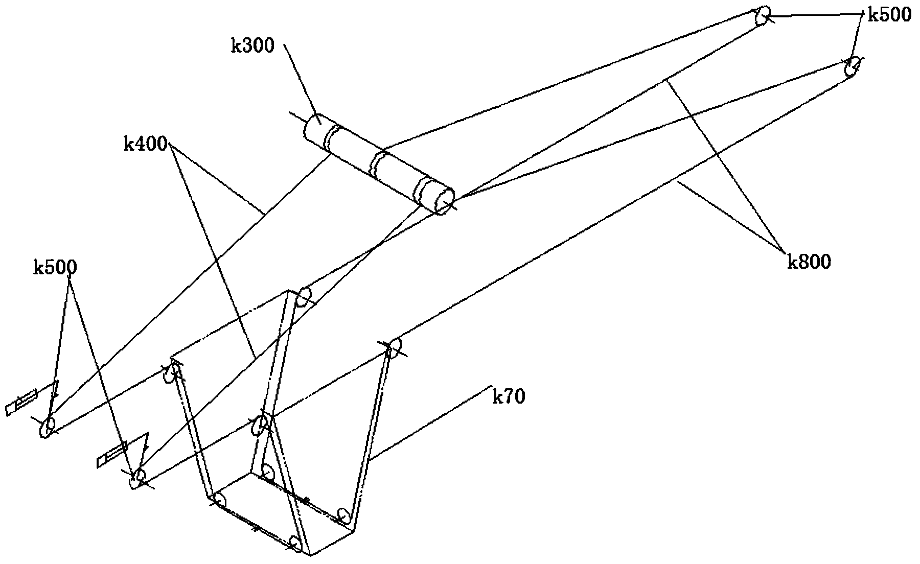
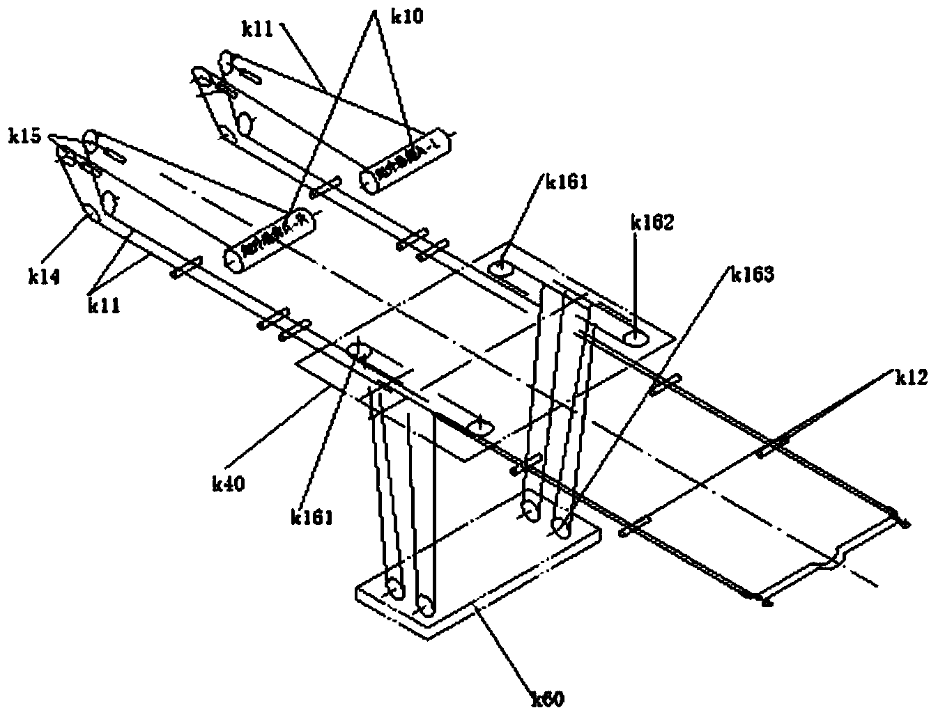
[0069] This embodiment provides a winding system that can be used for upper and lower trolleys in a through-type double-car energy-saving quay crane system. The winding system can be used in the cooperative use of the through-type double-car and quay crane. Specifically, the winding system is suitable for use in the following girder structures, such as Figure 7 , Figure 8 and Figure 21 As shown, the girder structure includes a first girder s1 and a second girder s2 arranged in parallel; a first guide rail s3 and a second guide rail s4 are provided on the opposite inner sides of the first girder s1 and the second girder s2, so The first guide rail s3 and the second guide rail s4 jointly form a first guide rail structure supporting the operation of the upper trolley k40; the outside of the first beam s1 and the second beam s2 are provided with a third guide rail s5 and a second guide rail. The four guide rails s6, the third guide rail s5 and the fourth g...

Example Embodiment

[0097] Example 2

[0098] like Figure 10 As shown, this embodiment provides a potential energy compensation system in a traversable double-car energy-saving quayside crane system, including a balance weight a5, a potential energy compensation winding system a4, and a potential energy compensation wire rope a3.

[0099] Wherein, the lower end of the potential energy compensation winding system a4 is connected to the balance weight a5 for transmitting driving force to make the balance weight a5 rise or fall; one end of the potential energy compensation wire rope a3 is connected to the potential energy compensation winding system a4 The upper end and the other end are adapted to be connected with a driving force source for transmitting the driving force to make the potential energy compensation winding system a4 act, so that the balance weight a5 rises or falls.

[0100] The potential energy compensation system of this embodiment also includes a lifting drum a1 for the lifting ...

Example Embodiment

[0120] Example 3

[0121] As an alternative form of the potential energy compensation system in embodiment 2, this embodiment provides a potential energy compensation system, in this embodiment, such as Figure 11 As shown, the potential energy compensation system is provided in two sets, which are respectively arranged on the left side and the right side of the trolley spreader a6, and the four potential energy compensation steel wire ropes of each set of the potential energy compensation system pass through the redirection pulley Winding on the lifting drum on the corresponding side, that is, the potential energy compensation steel wire rope on the left side of the spreader is wound on the first lifting drum through the redirection pulley, and the potential energy compensation steel wire rope on the right side of the spreader is Winding to the pulley on the second lifting drum.

[0122] It should be noted that, in each of the potential energy compensation systems in this em...


PUM


Abstract

The invention discloses an energy-saving quayside container crane system provided with crossing type double trolleys. The energy-saving quayside container crane system comprises an upper trolley, a lower trolley and potential energy compensation systems, wherein the upper trolley and the lower trolley are mounted on a girder structure; each potential energy compensation system comprises a counterweight, a potential energy compensation winding system and a potential energy compensation steel wire rope, and the potential energy compensation winding system is used for transmitting driving force to lift and drop the counterweight; each potential energy compensation system further comprises a lifting winding drum allowing joint winding of a lifting steel wire rope and the potential energy compensation steel wire rope; the winding positions of each compensation steel wire rope and each lifting steel wire rope on the hoisting winding drum do not interfere with each other and are opposite; and the potential energy compensation systems comprise an upper trolley potential energy compensation winding subsystem and a lower trolley potential energy compensation winding subsystem. According to the system, forward torque generated by dead weight of lifting appliances is offset by backward torque generated by the counterweights, the overall energy consumption of the quayside container crane is reduced, further, one lifting winding drum is shared by each compensation steel wire rope and the corresponding lifting steel wire rope, accordingly, the structure is simplified, the cost is reduced, and rope winding is relatively simple and easy to achieve; and the potential energy compensation systems comprise the upper trolley potential energy compensation winding subsystem and the lower trolley potential energy compensation winding subsystem, so that the lifting appliances of the upper trolley and the lower trolley are compensated respectively.

Description

technical field [0001] The invention relates to an energy-saving quay bridge system with double trolleys, which belongs to the technical field of heavy object lifting. Background technique [0002] In the prior art, the method of setting up multiple trolleys in the container quay crane system to run simultaneously is often used to improve the loading and unloading efficiency of the container quay crane; however, the operation mode of crossing double trolleys is mostly used at present. [0003] For example, Chinese patent document CN101323415A discloses a kind of through-type double trolley bridge type crane, which includes a cart and a main beam arranged on the cart, and also includes: a first load trolley, the first load trolley includes a pick-up device, a left lobe The vehicle frame and the right lobe frame, the pick-up device is suspended on the left lobe frame and the right lobe frame through the hoisting sling, and the hoisting sling of the first load trolley and the p...

Claims


Application Information

Patent Timeline
IPC IPC(8): B66C17/00B66C5/02B66C9/10B66C9/00
CPCB66C5/02B66C9/00B66C9/10B66C17/00B66C2700/01
Inventor 赵迎九郑雪峰杜蔚琼倪华肖强皮岩峰
Owner 华电蓝科科技股份有限公司
Why Eureka
Try Eureka