Magnetic suspension type horizontal tuned mass damper

A technology of tuning mass damping and magnetic levitation, applied in bridge parts, building components, bridges, etc., can solve problems such as the decline of design and control effects, and achieve the effects of convenient adjustment and maintenance, good work, and ingenious structural design.

Active Publication Date: 2015-01-07
NORTH CHINA UNIV OF WATER RESOURCES & ELECTRIC POWER
View PDF5 Cites 21 Cited by
  • Summary
  • Abstract
  • Description
  • Claims
  • Application Information

AI Technical Summary

Problems solved by technology

[0004] The present invention aims at the problem that TMDs using guide devices generally have unavoidable frictional damping in the prior art, especially horizontal TMDs, and the design and control effect of friction on TMDs is reduced, and proposes a magnetic levitation horizontal tuned mass damper

Method used


Image

  • Magnetic suspension type horizontal tuned mass damper
  • Magnetic suspension type horizontal tuned mass damper
  • Magnetic suspension type horizontal tuned mass damper

Examples


Embodiment 1

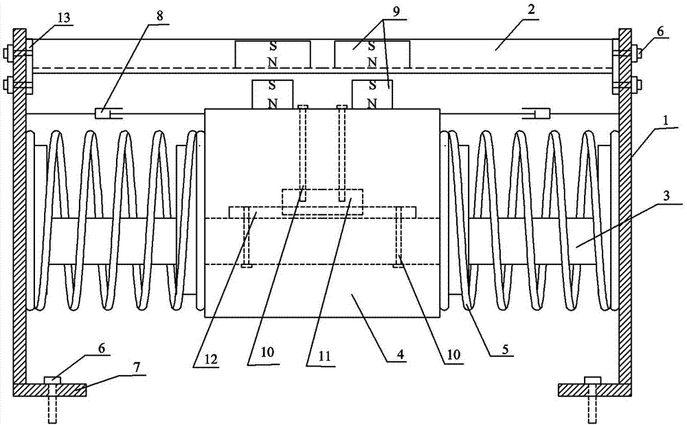
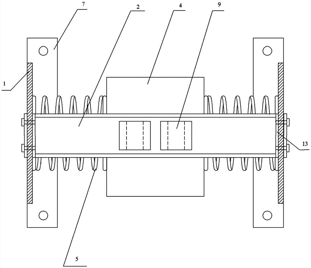
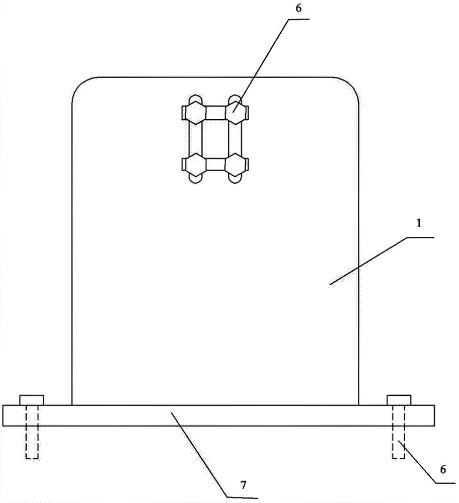
[0021] Example 1: Combining Figure 1-Figure 3 , a magnetically suspended horizontally tuned mass damper, comprising a frame body and a mass block arranged in the middle of the frame body, wherein the frame body includes vertical plates arranged on both sides, and an upper beam and a lower beam are connected between the vertical plates, and the vertical plate The lower end of the plate is provided with a support base plate, the upper beam is made of channel steel, and the upper beam and the vertical plate are fixedly connected by a backing plate and bolts and nuts. It can be adjusted up and down in the shaped hole. The rectangular permanent magnet is installed at the bottom of the channel steel; the lower beam is made of square steel, and an iron ring is arranged between the lower beam and the vertical plate. The outer diameter of the iron ring is slightly smaller than the inner diameter of the compression spring. Welding; a linear guide rail is fixed above the middle of the ...

Embodiment 2

[0023] Embodiment 2, no figure, the same part as Embodiment 1 will not be repeated, the difference is that the number of rectangular permanent magnets fixedly installed on the mass block is 2, and the number of rectangular permanent magnets corresponding to the upper beam is 1, the magnetization direction of the rectangular permanent magnet is the same, the length of the rectangular permanent magnet installed on the upper beam is equal to the length of the 2 rectangular permanent magnets on the mass block plus the distance between the 2 rectangular permanent magnets, plus damping 2 times the amplitude of the damper; the damper is a magnetorheological damper.


PUM


Abstract

The invention belongs to the field of horizontal vibration control devices for civil engineering structures and particularly relates to a magnetic suspension type horizontal tuned mass damper. The magnetic suspension type horizontal tuned mass damper comprises a frame and a mass block in the middle of the frame, the frame comprises vertical plates on two sides, an upper cross beam and a lower cross beam are connected between the vertical plates, and support bottom plates are arranged at the lower ends of the vertical plates. A linear guide rail and a slider sliding along the linear guide rail are fixed above the middle of the lower cross beam, the mass block is fixedly connected with the slider through screw nuts, a damper is connected between the mass block and each vertical plate, a pressure spring sleeving the lower cross beam is mounted between the mass block and each vertical plate, a first rectangular permanent magnet is fixedly mounted at the top of the mass block, and a second rectangular permanent magnet is arranged on the upper cross beam corresponding to the first rectangular permanent magnet. According to the magnetic suspension principle, friction between the slider and the linear guide rail is reduced to enable normality in operation of the horizontal TMD (tuned mass damper) even in weak vibration environment, flexibility and reliability of the TMD are improved, and service lives of the slider and the linear guide rail are prolonged owing to low friction.

Description

technical field [0001] The invention belongs to the field of horizontal vibration control devices suitable for civil engineering structures, and in particular relates to a magnetically suspended horizontally tuned mass damper. Background technique [0002] In recent years, with the development of high-rise, long-span and soft civil engineering structures, the dynamic response of structures under wind, earthquake and pedestrian loads has been paid more and more attention. Structural vibration control technology, especially structural passive vibration control technology has been widely used in civil engineering structures. Tuned mass damper (TMD), also known as dynamic vibration absorber in the early days, is a common and important form of passive vibration control technology, and has a wide range of applications in the field of vibration control of civil engineering structures. Typical engineering applications of TMD in building structures include the 570-ton ball suspended...

Claims


Application Information

Patent Timeline
Patent Type & Authority Applications(China)
IPC IPC(8): E04B1/98E01D19/04
Inventor 汪志昊陈政清吴泽玉王玉柱贾美晨张闯刘飞
Owner NORTH CHINA UNIV OF WATER RESOURCES & ELECTRIC POWER
Why Eureka
Try Eureka