Check patentability & draft patents in minutes with Patsnap Eureka AI!

Soil cabin structure of shield machine

A technology of shield machine and soil tank, which is applied to earth-moving drilling, mining equipment, tunnels, etc., can solve problems such as affecting the construction quality and progress of the project, easily forming mud cakes, affecting the discharge of slag, etc., and achieves easy installation. , the effect of high work efficiency and low manufacturing cost

Inactive Publication Date: 2015-01-07
WUXI AOYUTE NEW TECH DEV
View PDF6 Cites 4 Cited by
  • Summary
  • Abstract
  • Description
  • Claims
  • Application Information

AI Technical Summary

Problems solved by technology

[0002] When the earth pressure balance shield machine is carrying out tunnel excavation construction, the soil cut by the cutter head will accumulate in the middle and lower part of the soil cabin after entering the soil cabin, and then sent out by the screw conveyor to the belt conveyor inside the shield machine. If the muck accumulated in the soil tank is not fully stirred, it is easy to form a mud cake, which will affect the discharge of the muck. In severe cases, it will affect the quality of the construction and the progress of the construction.

Method used


Image

  • Soil cabin structure of shield machine

Examples


Embodiment Construction

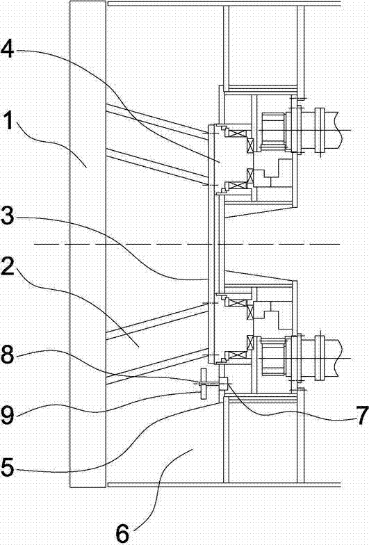
[0010] Such as figure 1 As shown, the soil cabin structure of a shield machine of the present invention includes a cutter head 1, a connecting arm 2, and a connecting flange 3. The cutter head 1 and the connecting flange 3 are disc-shaped, and the cutter head 1 Welded together with the connecting flange 2 through the connecting arm 2, the connecting flange 3 is fixedly connected to the force transmission ring 4, the outer periphery of the force transmission ring 4 is a bulkhead 5, and the bulkhead 5 and the cutter head 1 The space between forms the soil cabin 6, and the lower end of the bulkhead 5 is fixedly installed with a driving motor 7 at an appropriate position, and the side of the driving motor 7 facing the soil cabin 5 is connected with a drive shaft 8. A stirring wing 9 is fixed in the circumferential direction.

[0011] The drive motor 7 is enclosed and installed inside the bulkhead 5 .

[0012] When the dregs in the soil cabin 5 began to accumulate, the drive moto...


PUM


Abstract

The invention discloses a soil cabin structure of a shield machine. A drive motor is fixedly installed at the proper position of the lower end of the soil cabin wall, the side facing a soil cabin, of the drive motor, is connected with a drive shaft, and a stirring wing is fixed in the peripheral direction of the drive shaft. Therefore, when fully stirred muck is fed into the soil cabin through cutting, the drive motor can be started and drives the stirring wing to rotate and stir the muck through the drive shaft. Mud cake forming is thoroughly prevented, the flowing and discharging speed of the muck is further improved, and the working efficiency is high. In addition, the soil cabin structure of the shield machine further has the advantages of being low in manufacturing cost, easy to install, convenient to operate and the like.

Description

technical field [0001] The invention relates to the technical field of tunnel construction equipment, in particular to an earth cabin structure of a shield machine. Background technique [0002] When the earth pressure balance shield machine is carrying out tunnel excavation construction, the soil cut by the cutter head will accumulate in the middle and lower part of the soil cabin after entering the soil cabin, and then sent out by the screw conveyor to the belt conveyor inside the shield machine. If the muck accumulated in the soil tank is not fully stirred, mud cakes will easily form, which will affect the discharge of muck. In severe cases, it will affect the quality of construction and the progress of construction. Contents of the invention [0003] The problem to be solved by the present invention is to overcome the deficiencies in the background technology and provide a soil chamber structure of a shield machine. The soil chamber structure of this shield machine is ...

Claims


Application Information

Patent Timeline
Patent Type & Authority Applications(China)
IPC IPC(8): E21D9/08
CPCE21D9/08
Inventor 张鹏其他发明人请求不公开姓名
Owner WUXI AOYUTE NEW TECH DEV
Features
  • R&D
  • Intellectual Property
  • Life Sciences
  • Materials
  • Tech Scout
  • Unparalleled Data Quality
  • Higher Quality Content
  • 60% Fewer Hallucinations
Learn More