Multi-unit fume exhaust device

A fume exhaust device and multi-type technology, applied in heating methods, oil fume removal, household heating and other directions, can solve the problems of yellowing of roasted paste, inconvenient operation, large temperature fluctuation, etc., to improve quality, reduce waste, prevent The effect of heat dissipation

Active Publication Date: 2015-01-07
GUANGZHOU BAKE OVEN MACHINERY
View PDF8 Cites 2 Cited by
  • Summary
  • Abstract
  • Description
  • Claims
  • Application Information

AI Technical Summary

Problems solved by technology

[0003] The top of the existing ovens is generally equipped with a natural smoke exhaust type or an induced draft fan mechanical smoke exhaust device, which cannot control the amount of smoke exhausted, that is to say, it cannot discharge the steam and steam in the furnace chamber according to the specific production conditions. Hot air, inconvenient to operate
[0004] For example, in the case of natural smoke exhaust, when baking foods with high water content or foods with low water content in the finished product, the natural smoke and moisture discharge often fail to meet the requirements, causing the water vapor inside the furnace to If the ratio is too high, the food will appear uneven in color and high in moisture
[0005] In the case of using the induced draft fan to mechanically exhaust smoke, although it can ensure that more water and waste can be discharged in time, but at the same time, a large amount of hot air will be discharged from the smoke exhaust device, which not only causes waste of energy, but also causes airflow in the furnace chamber. Unstable, resulting in large fluctuations in the temperature in the oven, causing the food to sometimes turn white in color and sometimes burnt to yellow

Method used


Image

  • Multi-unit fume exhaust device
  • Multi-unit fume exhaust device

Examples


Embodiment Construction

[0021] Below, in conjunction with accompanying drawing and specific embodiment, the present invention is described further:

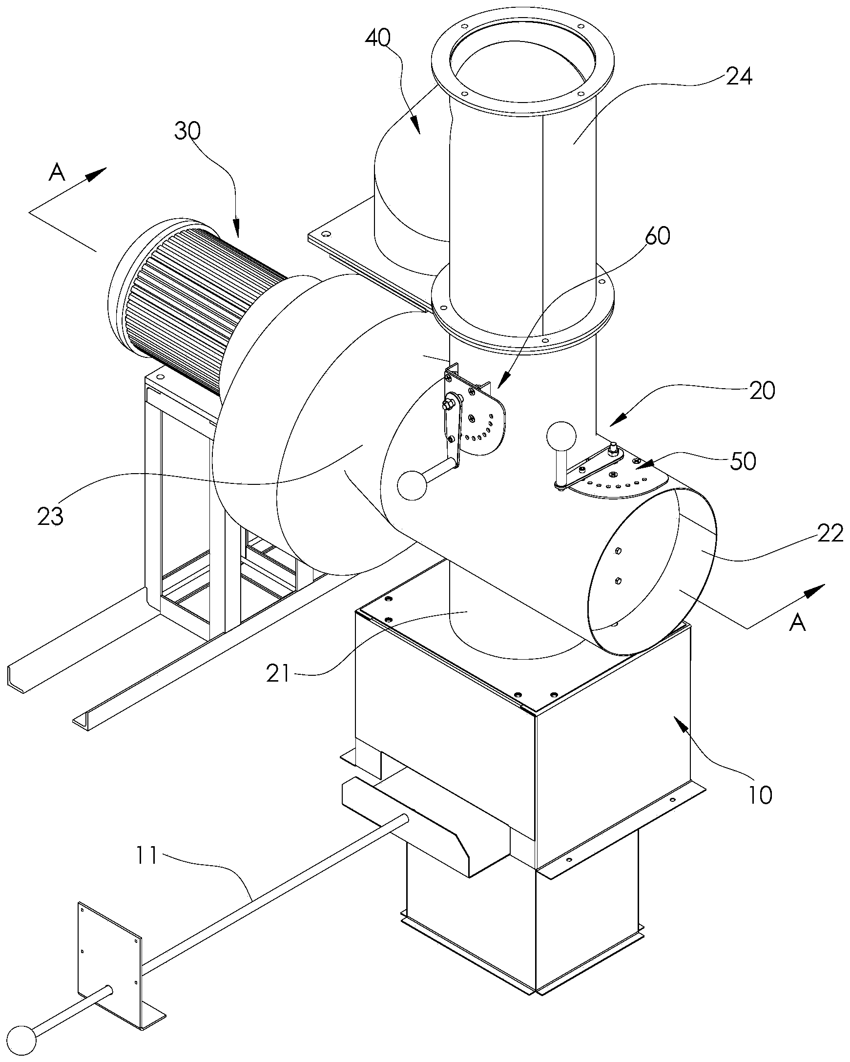
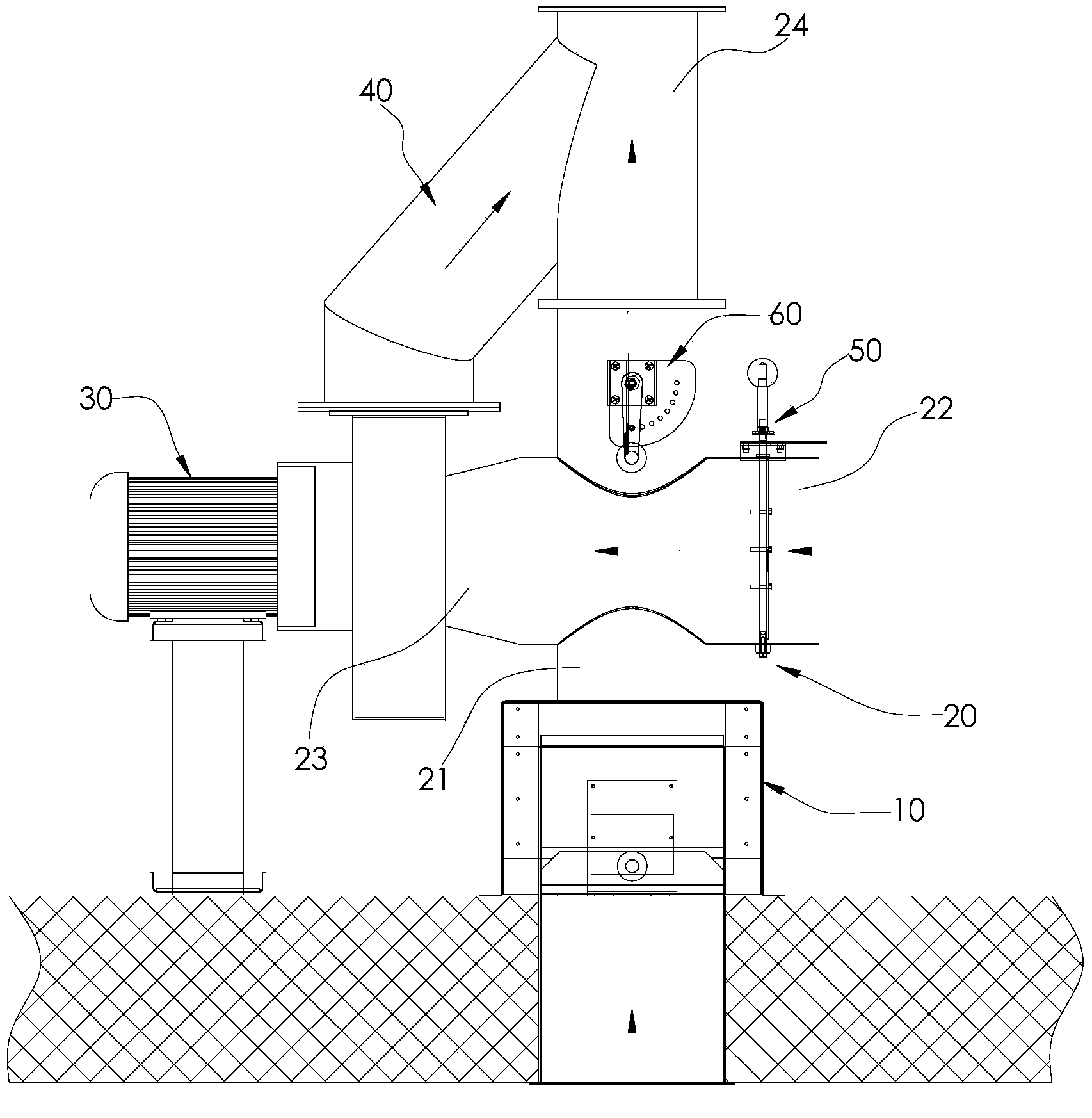
[0022] Such as figure 1 , 2 As shown, it is a multi-component smoke exhaust device of the present invention, which includes a four-way pipe 20, a first control valve 50, a second control valve 60, an induced draft fan 30 and a communication pipe 40, and the four-way pipe 20 has four The four joints are respectively the first joint 21 communicated with the smoke exhaust pipe of the oven, the second joint 22 communicated with the external environment, the third joint 23 facing the second joint 22, and the first joint 23 connected with the first joint. 21 is facing the fourth joint 24, wherein the first joint 21 is used to introduce the flue gas inside the oven into the inside of the four-way pipe 20, and the second joint 22 is used to transport the air in the external environment to the four-way pipe 20 , the fourth joint 24 is used to discharge the smo...


PUM


Abstract

A multi-unit fume exhaust device comprises a four-way pipe, a first control valve, a second control valve, an induced draft fan and a communicating pipe, wherein the four-way pipe comprises a first connector communicated with a fume exhaust pipe of an oven, a second connector communicated with the outside environment and used for delivering outside air into the four-way pipe, a third connector right opposite to the second connector and a fourth connector which is right opposite to the first connector and used for exhausting fume; the first control valve is mounted in the second connector and used for controlling outside air inflow; the second control valve is mounted in the fourth connector and used for controlling the fume output; an air inlet end of the induced draft fan is communicated with the third connector; and one end of the communicating pipe is communicated to an air outlet end of the induced draft fan, the other end is communicated to the fourth connector, and the position where the communicating pipe is connected with the fourth connector is located outside the second control valve. Natural fume exhaust, mechanical fume exhaust and an exhaust mode combining the natural fume exhaust and the mechanical fume exhaust can be achieved according to actual baking requirement, so that the food baking quality is improved, and energy waste is reduced.

Description

technical field [0001] The invention relates to the technical field of food baking, in particular to a multi-component smoke exhaust device. Background technique [0002] An oven is a device that uses hot air convection, heat radiation, and heat conduction to cook food. It can also be used to generally refer to a device that uses hot gas convection, heat radiation, and heat conduction for high-temperature treatment. The oven is generally a closed or semi-closed structure. , when the product is baked, the water vapor formed by the evaporation of product water and the exhaust gas generated by the burner are discharged through the exhaust pipe on the top of the oven, so that the oven always maintains proper humidity and clean air, so that the baked food can be baked optimally. quality. [0003] The top of the existing ovens is generally equipped with a natural smoke exhaust type or an induced draft fan mechanical smoke exhaust device, which cannot control the amount of smoke e...

Claims


Application Information

Patent Timeline
Patent Type & Authority Applications(China)
IPC IPC(8): F24C15/20
CPCF24C15/2021
Inventor 邵鸿飞杨勇军
Owner GUANGZHOU BAKE OVEN MACHINERY
Why Eureka
Try Eureka