
Device for measuring heat conductivity coefficient of liquid on basis of transient plane source method

A technology of transient plane and thermal conductivity, applied in the direction of material resistance, etc., can solve the problems of high liquid thermal conductivity measurement results and increased data dispersion rate, and achieve the effects of suppressing natural convection, high output power, and high reliability

Active Publication Date: 2015-01-07
HARBIN INST OF TECH
View PDF4 Cites 9 Cited by
  • Summary
  • Abstract
  • Description
  • Claims
  • Application Information

AI Technical Summary

Problems solved by technology

[0005] The purpose of the present invention is to solve the existing transient plane heat source method for measuring the thermal conductivity of liquids, where the probe is placed vertically and natural convection heat transfer is formed on the surface of the probe, and the use of low output power will lead to an increase in the data dispersion rate, resulting in a decrease in the thermal conductivity of the liquid. In order to solve the problem of high measurement results, a device for measuring the thermal conductivity of liquids based on the transient plane heat source method is provided

Method used


Image

  • Device for measuring heat conductivity coefficient of liquid on basis of transient plane source method

Examples


specific Embodiment approach 1

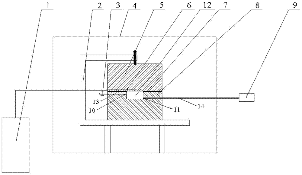
[0017] Specific Embodiment 1: This embodiment is a device for measuring liquid thermal conductivity based on the transient plane heat source method, including a computer 1, a sample holder 2, a valve 3, a sample chamber 4, a solid standard sample 5, a probe 6, and a gasket 7 , aluminum alloy 8 and liquid injector 9, liquid pool 12, first plastic tube 13 and second plastic tube 14;

[0018] The sample chamber 4 is provided with a sample holder 2, and the aluminum alloy 8 is arranged on the sample holder 2; the upper end of the aluminum alloy 8 is provided with a liquid pool 12; the two ends of the liquid pool 12 are provided with a first small hole on the wall of the pool 10 and the second small hole 11; one end of the first plastic tube 13 communicates with the first small hole 10, and the other end of the first plastic tube 13 communicates with the valve 3; one end of the second plastic tube 14 communicates with the second small hole 11 is connected, and the other end of the ...

specific Embodiment approach 2

[0028] Embodiment 2: The difference between this embodiment and Embodiment 2 is that the length of the groove with a depth of 25 μm is equal to the length of the probe 6 . Other steps are the same as in the second embodiment.

specific Embodiment approach 3

[0029] Embodiment 3: This embodiment differs from Embodiment 1 or Embodiment 2 in that: the tip of the probe 6 is above the center of the liquid pool 12 . Other steps are the same as those in Embodiment 1 or 2.


PUM

PropertyMeasurementUnit
Depthaaaaaaaaaa
Radiusaaaaaaaaaa
Thermal conductivityaaaaaaaaaa

Abstract

The invention relates to a device for measuring a heat conductivity coefficient of liquid on the basis of a transient plane source method and relates to a measurement device for the heat conductivity coefficient. The invention aims to solve the problem that when an existing transient plane source method is adopted to measure the heat conductivity coefficient of the liquid, a probe is vertically placed, natural-convection heat transfer is formed on the surface of the probe and adoption of low output power can cause increase of a data dispersion ratio and causes an excessively high measurement result of the heat conductivity coefficient of the liquid. The device comprises a computer, a sample holder, a valve, a sample bin, a solid standard sample, a probe, a gasket, aluminum alloy and a liquid pool; the sample holder is arranged in the sample bin; the aluminum alloy is arranged on the sample holder; the liquid pool is formed at the upper end of the aluminum alloy; the gasket is arranged on the upper end face of the liquid pool; the solid standard sample is arranged on the upper end face of the gasket; the lower end face of the solid standard sample is provided with a groove with a depth of 25 micrometers; the probe is arranged inside the groove with the depth of 25 micrometers. The device provided by the invention is capable of measuring the heat conductivity coefficient of the liquid on the basis of the transient plane source method.

Description

technical field [0001] The invention relates to a measuring device for liquid thermal conductivity. Background technique [0002] Thermal conductivity is an important thermophysical parameter of materials, and a basic parameter to quantify heat transfer process and evaluate thermal properties of materials. It has a wide range of application backgrounds in engineering fields involving heat transfer. The accuracy of measured values ​​of thermal conductivity of liquid materials is crucial in industrial applications, especially for precise thermal design and specific thermal process research. Inaccurate thermal conductivity of liquids may lead to misjudgment of the dominant heat transfer mode, causing serious damage. mistake. [0003] According to the analysis of heat transfer characteristics, the current measurement methods of thermal conductivity can be roughly summarized as steady-state method and transient method. Although the steady-state method is simple to operate and e...

Claims


Application Information

Patent Timeline
IPC IPC(8): G01N27/18
Inventor 艾青胡振文夏新林孙创
Owner HARBIN INST OF TECH
Learn More