
Smart card chip packaging equipment

A technology for smart card chips and packaging equipment, applied in transportation and packaging, conveyor objects, electrical components, etc., can solve the problems of affecting packaging speed, packaging speed is not high enough, affecting chip position accuracy, etc., to improve position accuracy, improve packaging Speed, the effect of improving packaging accuracy

Active Publication Date: 2015-01-07
GUANGZHOU MINGSEN TECH CO LTD
View PDF4 Cites 11 Cited by
  • Summary
  • Abstract
  • Description
  • Claims
  • Application Information

AI Technical Summary

Problems solved by technology

[0003] In the existing chip supply device, the conveying direction of the chip tape is usually parallel to the conveying direction of the card, which has the following disadvantages: 1. In order to arrange the chip supply device, there is a large gap between the chip punching station and the chip packaging station. The distance between the package and the packaging device makes the stroke larger when the chip is moved from the punching station to the chip packaging station, which in turn affects the speed of packaging; The attitudes of the slots differ by 90°, so when transferring the chip to the packaging slot, it needs to be rotated by 90°, which not only affects the chip transfer speed, but also affects the positional accuracy of the chip when it is placed in the packaging slot
This chip supply device ensures that the posture of the cut chip is consistent with the posture of the packaging groove of the card of the chip packaging station, and there is no need to rotate 90 ° in the transfer process, but there are still the following deficiencies: 1. A traction wheel mechanism needs to be set between the cutting station and the chip packaging station, so the transfer of the chip is still relatively large, and the packaging speed is still not high enough; The positioning references of different cards are different, so it is not easy to ensure that the cut chip is parallel to the packaging groove in the card, which affects the packaging accuracy

Method used


Image

  • Smart card chip packaging equipment
  • Smart card chip packaging equipment
  • Smart card chip packaging equipment

Examples


Embodiment Construction

[0032] The present invention will be further described in detail below in conjunction with the embodiments and the accompanying drawings, but the embodiments of the present invention are not limited thereto.

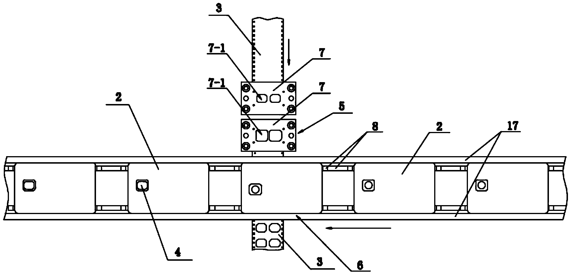
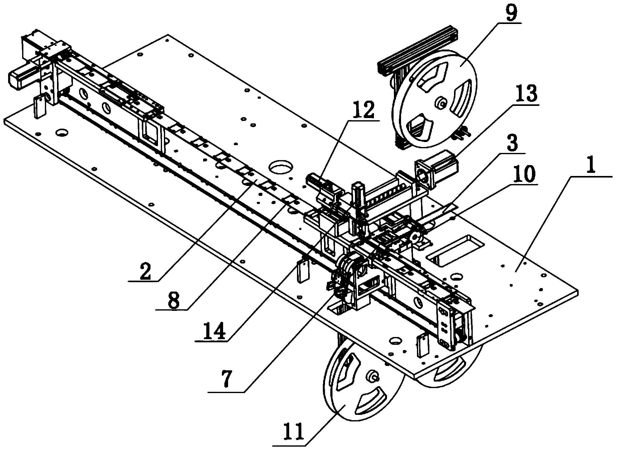
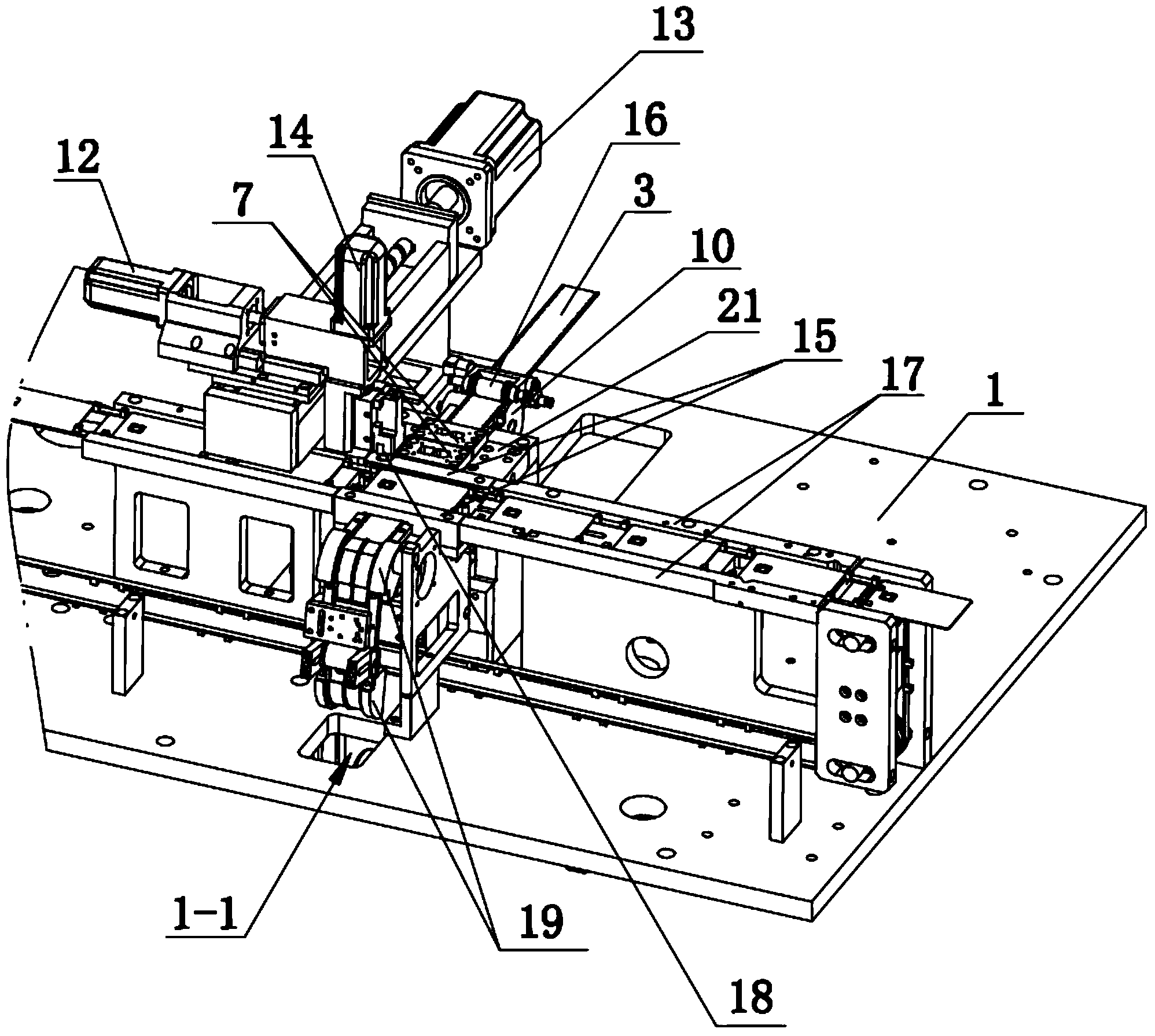
[0033] see Figure 1 to Figure 5 , The smart card chip packaging equipment of the present invention includes a workbench 1 and a card conveying device, a chip packaging device and a chip supply device arranged on the workbench 1 .

[0034] see Figure 1 to Figure 5 , the card conveying device includes a card conveying mechanism that conveys the cards 2 to be packaged to the packaging station 6 one by one in an intermittent conveying manner, and the card conveying includes a card conveying guide rail, a conveying belt 8 and a conveying motor, wherein the Conveyor belt 8 is circular structure, totally two, is provided with on each conveyer belt 8 and is used for pushing card 2 to move, and two conveyer belts 8 pushes card 2 to convey forward intermittently during work. T...


PUM


Abstract

The invention discloses smart card chip packaging equipment. The smart card chip packaging equipment comprises a working table, a card conveying device, a chip packaging device and a chip feeding device, wherein the card conveying device, the chip packaging device and the chip feeding device are arranged on the working table. The card conveying device comprises a card conveying mechanism used for intermittently conveying cards to be packaged to a packaging station one by one; the chip feeding device comprises a chip belt conveying mechanism, a blanking die and a blanking mechanism, and the chip belt conveying mechanism is used for conveying chips on a chip belt to a blanking station one by one; the chip packaging device comprises a packaging mechanism used for transferring the chips which have been blanked to the cards for packaging; the conveying direction of the chip belt conveying mechanism is perpendicular to the conveying direction of the card conveying mechanism, the chip belt penetrates through the position below the packaging station in the card conveying device, and the blanking station in the chip feeding device is arranged at the position tightly attached to the packaging station in the card conveying device. According to the smart card chip packaging equipment, the movement stroke of the chips is shortened, and the packaging speed is increased.

Description

technical field [0001] The invention relates to smart card production equipment, in particular to smart card chip packaging equipment. Background technique [0002] In the smart card production process, chips need to be packaged on the card, and the chip packaging is completed by assembly line operation. The packaging process is as follows: the cards to be packaged are transported to the packaging station one by one, and the chip supply device continuously provides the cut chips. , the chip packaging device picks up the chip from the chip supply device and packages it into the packaging groove of the card. The working process of the chip supply device is as follows: the chips before packaging are arranged on the chip tape at a certain distance, and the chips need to be cut from the chip tape according to the set size during packaging, and the cut chips are sucked by the chip packaging device And move it to the card for packaging; the cutting of the chip is completed by the ...

Claims


Application Information

Patent Timeline
IPC IPC(8): H01L21/67H01L21/68H01L21/677
CPCH01L21/67121H01L21/67742H01L21/68H01L2221/67
Inventor 王开来
Owner GUANGZHOU MINGSEN TECH CO LTD
Learn More