Sintering device and sintering method using induction heating

A technology of a sintering device and a sintering method, which is applied to lighting and heating equipment, process efficiency improvement, furnace components, etc., can solve problems such as increasing flame propagation speed, environmental pollution, etc., and achieve the effect of reducing the amount of coke

Inactive Publication Date: 2015-01-07
POSCO
View PDF7 Cites 3 Cited by
  • Summary
  • Abstract
  • Description
  • Claims
  • Application Information

AI Technical Summary

Problems solved by technology

In addition, a large amount of carbon dioxide (CO 2 ) leading to environmental

Method used


Image

  • Sintering device and sintering method using induction heating
  • Sintering device and sintering method using induction heating
  • Sintering device and sintering method using induction heating

Examples


Example Embodiment

[0043] First of all, it should be noted that when adding labels to the components of each figure, although they are labelled on other figures, try to give the same labels to the same components. In addition, when describing the present invention, detailed descriptions of known functions and structures introduced herein will be omitted to avoid obscuring the subject of the present invention.

[0044] Hereinafter, exemplary embodiments of the present invention will be described in detail with reference to the accompanying drawings.
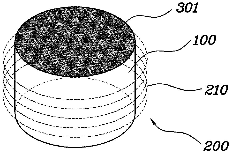
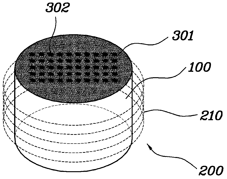
[0045] figure 1 with figure 2 The sintering device using induction heating according to the first embodiment of the present invention is shown.

[0046] The sintering device and method using induction heating according to the present invention uses the change of the magnetic field to cause heating of the highly conductive material included in the coking ore through magnetic induction, so that the coking ore is sintered.

[0047] Such as figure 1 As shown...


PUM


Abstract

Disclosed are a sintering device and a sintering method using induction heating, wherein a raw ore can be heated by inducing the heating of a highly conductive material included in the raw ore through magnetic inductance of an induction coil. The sintering device using induction heating of the present invention manufactures a sintered ore by inductively heating a raw ore, comprising: an induction case; and a heat inducing body which is mounted in the induction case and induces, through magnetic induction, the heating of the raw ore that is accommodated within the induction case or penetrates the induction case.

Description

technical field [0001] The present invention generally relates to a sintering apparatus and method using induction heating, and more particularly to a sintering apparatus and method using induction heating capable of inductively heating a highly conductive material included in raw ore through magnetic induction to sinter the raw ore. Background technique [0002] Generally, a sintering process performed on a sintering facility in a steelmaking plant is a process of melting a mixed material as ore powder to produce a sintered ore having a particle size within a predetermined range. The produced sinter is charged into a blast furnace as one of the main raw materials for producing steel products. [0003] For example, as in Figure 11 In a typical sintering process shown in , different materials, ie mineral powder and coke powder, are discharged from respective storage bins 10 in a predetermined ratio, mixed in a mixer 11 and stored in a hopper 12 . The mixed material in the h...

Claims


Application Information

Patent Timeline
IPC IPC(8): C22B1/16F27B21/08B22F3/10
CPCB22F3/10F27D99/0006C22B1/16B22F2999/00B22F3/003F27D2099/0015F27B21/06Y02P10/25B22F2202/07F27B19/00
Inventor 姜荣柱周东宣申东烨徐正道
Owner POSCO
Why Eureka
Try Eureka