Arrangement for mounting counter-rotatable parts of an energy system

A technology of supporting components and components, which is applied in the direction of anti-centrifugal rotating parts, rotating bearings, engine components, etc., can solve problems such as rolling bearing difficulties, and achieve the effect of improving radial load

Active Publication Date: 2015-01-07
IMO HOLDING GMBH
View PDF10 Cites 8 Cited by
  • Summary
  • Abstract
  • Description
  • Claims
  • Application Information

AI Technical Summary

Problems solved by technology

Although such devices have proven to be very stable in practice, it is difficult to assemble rolling bearings with a total of at least three rolling element rows

Method used


Image

  • Arrangement for mounting counter-rotatable parts of an energy system
  • Arrangement for mounting counter-rotatable parts of an energy system
  • Arrangement for mounting counter-rotatable parts of an energy system

Examples


Embodiment Construction

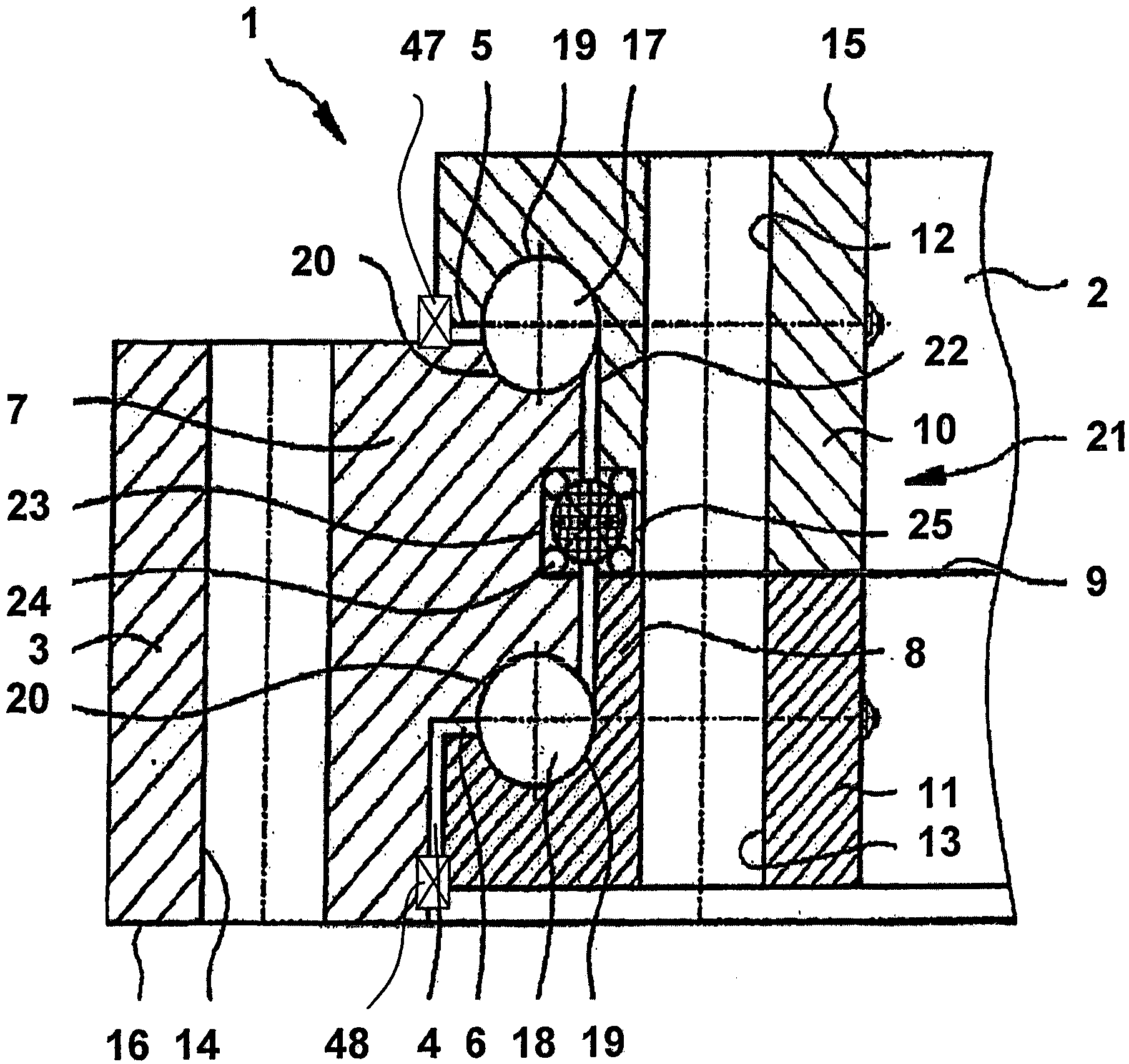
[0065] according to figure 1 A cross section through the rolling bearing 1 shows two ring-shaped coupling elements 2 , 3 which are arranged radially alternately and at least partially overlap each other in the axial direction. However, such an arrangement is not limited to two coupling elements 2, 3, for example, it can be arranged radially according to figure 1 Inside the inner coupling element 2, a third coupling element is arranged, which for example can have a relative figure 1 The middle outer coupling element 3 has a mirror-reversed cross-section and can also be designed similarly to the outer coupling element 3 with regard to the gap geometry and raceway geometry.

[0066] figure 1 The two coupling elements 2 , 3 are separated from each other by a gap 4 . However, the gap 4 does not follow the course of a purely cylindrical surface, but also has sections 5 , 6 in which the course of the gap also has a more or less pronounced radial component. Here too, the two coupl...


PUM


Abstract

The invention relates to a roller bearing arrangement (1, 26, 31, 34, 36, 37), preferably a large-scale roller bearing with a diameter of 0.5 m or more, for mounting parts of an energy system, in particular as blade bearings for a wind turbine, comprising at least two annular counter-rotatable elements (2, 3), arranged concentrically to one another and one inside another at least in areas, for connecting to counter-rotatable parts of the energy system. Two counter-rotatable connecting elements (2, 3) are separated from one another by a gap (4) and overlap one another radially, at least in part. Furthermore, at least two rows of rolling bodies (17, 18) are provided in the area of the gap (4) in radially overlapping areas of the annular connecting elements (2, 3), each row rolling along two tracks (19, 20) overlapping one another in the radial direction at least in areas. One or more tracks (19, 20) for rolling bodies (17, 18) are arranged in radially overlapping sections (5, 6) in such a manner that the angle of support, which is enclosed by the connection line between the centres of the contact points of a rolling body (17, 18) with the two tracks thereof opposite the ring plane, is greater than or equal to 45°, with the result that such an axial roller bearing is used for transmission of predominantly axially acting force components. At least one additional bearing for transmission of predominantly radially acting force components is provided, the support angle of which is less than 45°, preferably 25° or less, in particular 10° or less, wherein at most such tracks for radial roller bearings, the maximum distance of which perpendicular to the track surface is equal to or less than 25% of the largest distance perpendicular to the track surface between two tracks of an axial roller bearing row, are introduced directly into the annular connection elements (2, 3).

Description

technical field [0001] The invention is directed to a rolling bearing arrangement, preferably a large rolling bearing, with a diameter of 0.5 m or more, for supporting mutually rotatable parts of an energy plant, in particular as a blade bearing of a wind power plant, which has at least two mutually rotatable Concentrically and at least partially staggered, annular mutually rotatable elements for coupling the mutually rotatable parts of an energy unit, wherein the two mutually rotatable coupling elements are separated from each other by a gap and radially at least partially overlap each other, wherein in the region of the gap in the region of the radial overlap of the annular coupling element there are also at least two rows of rolling elements which overlap each other at least partially in the radial direction along two The raceway rolls, where one or more raceways for the rolling elements are arranged in radially overlapping sections such that between the centers of the cont...

Claims


Application Information

Patent Timeline
Patent Type & Authority Applications(China)
IPC IPC(8): F16C19/18F16C19/49F16C19/54F16C21/00
CPCF16C19/49F16C19/188F16C19/545F16C21/00F16C19/505F16C2300/14F16C2360/31F03D80/70Y02E10/72
Inventor 埃里克·卢斯胡贝图斯·弗兰克福尔克尔·迪茨
Owner IMO HOLDING GMBH
Why Eureka
Try Eureka