
Floating ball separating method of water collecting device of water purifier

A water collecting device and separation method technology, applied in separation methods, chemical instruments and methods, filtration and separation, etc., can solve the problem that the water collector affects the development of water purifier sewage collection and leakage alarm technology, affects the water collection capacity of the water collector, Affecting problems such as appearance and structure design, to achieve the effect of easy maintenance and cleaning of the machine, convenient maintenance, and high product quality

Active Publication Date: 2015-01-14
杜也兵
View PDF4 Cites 0 Cited by
  • Summary
  • Abstract
  • Description
  • Claims
  • Application Information

AI Technical Summary

Problems solved by technology

Since the floating ball channel is only involved in the process of removing the water collector, the floating ball channel is too low to affect the water collection capacity of the water collector; while the floating ball channel is too high to increase the water collection volume, resulting in waste of space and seriously affecting the appearance and structural design
In addition, the mode of first lowering the water level through the sealed discharge port designed on the water collector and then moving it out of the machine base is disadvantageous in that it is inconvenient to operate. The water in the container is led to another container
The above-mentioned water collector removal problem and defects caused by the floating ball seriously affect the development of water purifier sewage collection and water leakage alarm technology

Method used


Image

  • Floating ball separating method of water collecting device of water purifier

Examples


Embodiment 1

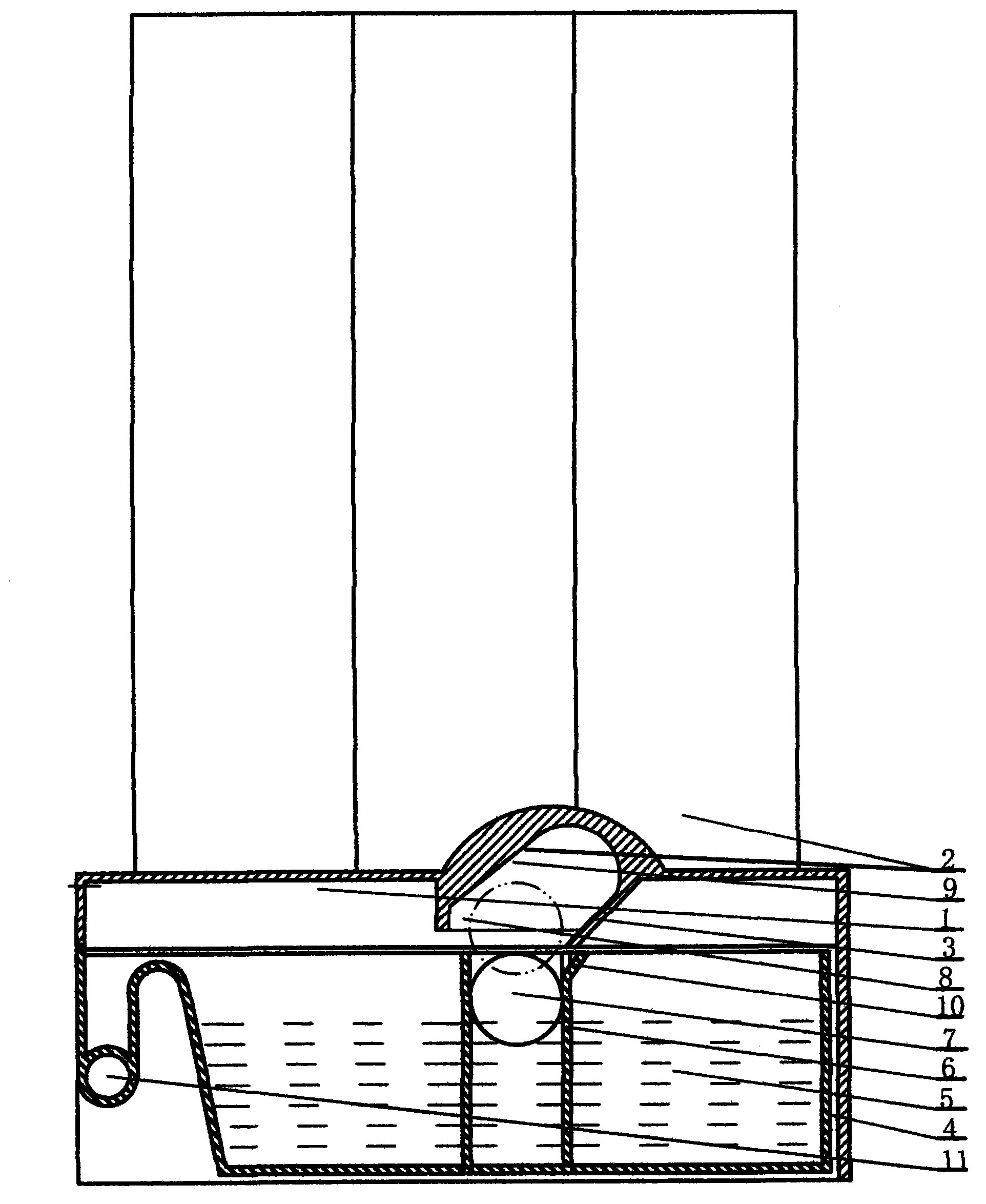
[0016] Example 1. This embodiment is the best embodiment. The base 1 is an injection molded part, including upper and lower parts. The upper part is provided with double rows of open filter cartridges 2 in a rectangular layout. The number of open filter cartridges 2 is 6, and the intersection of the 4 filter cartridges constitutes Set the position of avoidance space 9. In this case, only the bottom part of the filter cartridge related to this avoidance space 9, and the support are sectioned, and the filter cartridge inlet and outlet that are not related to this case are not marked. The open filter cartridge 2 adopts an inner cavity with a large upper part and a smaller lower part to facilitate manufacture. The upper port of the open filter cartridge 2 is screwed and matched with the screw cap and seals the gap with a seal, and its lower end bottom is connected with the machine base 1 provided with the filter gall interface to form a one-piece filter cartridge. The lower par...

Embodiment 2

[0027] Example 2. On the basis of the principle of embodiment 1, the lower machine base 2 with the floating ball avoiding the through hole and the closed filter gall with the water inlet and outlet are adopted. The closed filter gall is fixed above the lower machine base, and its water ports are connected by pipelines to form a filter channel. The lower end of the avoidance through hole as the floating ball avoidance space 9 is arranged along the limit structure and corresponds to the water collection container; its upper end leads to the upper surface of the lower machine base.

[0028] The micro switch as alarm switch (not marked) is provided with an arc-shaped trigger swing arm. The limit structure 8 and the micro switch are respectively located at the front and rear sides of the avoidance space 9 .

[0029] When the water to be collected by the machine flows into the water collecting container through the drain port, the floating ball 7 located in the floating ball colum...

Embodiment 3

[0035] Example 3. A vertical through hole is set on the base as an avoidance space 9; the water collecting container is provided with a porous movable floating ball bar with a built-in floating ball, and is inserted into the water collecting container 5 by the vertical through hole upper end of the base; The float bar of the float ball is then removed from the water collection container.


PUM


Abstract

The invention discloses a floating ball separating method of a water collecting device of a water purifier, which is related to the water treatment industry and particularly relates to deep purifying of drinking water. According to the floating ball separating method of the water collecting device of the water purifier, a water collecting container, a floating ball, an alarm switch, and a base provided with a water discharging hole are included, wherein the water collecting container is arranged at the bottom of the base and used for collecting accumulated water in a high place of the base in an abnormal operation state; the distance between the floating ball positioned in the water collecting container and the bottom surface of the container is changed under the action of water buoyancy until the alarm switch is triggered. A limit structure and an avoiding space which are arranged on the base are also included, wherein the limit structure and the avoiding space are positioned above the water collecting container, allowable horizontal and vertical displacements of the floating ball in a moving process of the water collecting container are controlled; the height between the upper end of the water collecting container and the height of the upper end of the avoiding space is equal to or greater than the diameter of the floating ball; in a process of forwards moving the water collecting container out of the base, the rear end of the water collecting container and the limit structure of the base are respectively in contact with two ends of the suspended floating ball and squeeze the floating ball to move up to enter the avoiding space until the floating ball moves out of the water collecting container.

Description

technical field [0001] The invention relates to the water treatment industry, and specifically relates to the deep purification of drinking water. Background technique [0002] Most of the medium and low-priced water purifiers use an open liner to configure a bare metal model. The machine structure in which the filter housing with built-in liner is hoisted under the machine base, although the filter housing can be reused, correspondingly reduces the cost of replacing the filter tube by 10-20% for consumers, but it also brings about a single product structure and difficulty in replacing the liner, etc. problem. Usually the water purifier is directly placed in the kitchen cabinet through the filter shell with built-in filter gall. When replacing the inner tank, the water purifier needs to be taken out and overhead to load and unload the filter gall in the lower filter cartridge. Because the water purifier with water is very heavy, and is involved by the water inlet and outle...

Claims


Application Information

Patent Timeline
Patent Type & Authority Applications(China)
IPC IPC(8): B01D35/14B01D35/16B01D37/04C02F1/00
CPCB01D29/11B01D29/60B01D29/66B01D35/1435B01D37/04B01D37/045C02F1/001
Inventor 杜也兵冉伊虹
Owner 杜也兵
Learn More