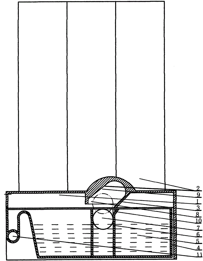
Floating ball separation method for water collecting device of water purifier
A technology of water collection device and separation method, which is applied in the direction of separation method, chemical instrument and method, filtration and separation, etc., can solve the problem that the water collector affects the sewage collection and leakage alarm technology development of the water purifier, affects the water collection capacity of the water collector, Affect the appearance and structure design and other issues, to achieve the effect of easy maintenance and cleaning machine, convenient maintenance and high product grade
- Summary
- Abstract
- Description
- Claims
- Application Information
AI Technical Summary
Problems solved by technology
Method used
Image
Examples
Embodiment 1
[0016] Example 1. This embodiment is the best embodiment. The base 1 is an injection molded part, including upper and lower parts. The upper part is provided with double rows of open filter cartridges 2 in a rectangular layout. The number of open filter cartridges 2 is 6, and the intersection of the 4 filter cartridges constitutes Set the position of avoidance space 9. In this case, only the bottom part of the filter cartridge related to this avoidance space 9, and the support are sectioned, and the filter cartridge inlet and outlet that are not related to this case are not marked. The open filter cartridge 2 adopts an inner cavity with a large upper part and a smaller lower part to facilitate manufacture. The upper port of the open filter cartridge 2 is screwed and matched with the screw cap and seals the gap with a seal, and its lower end bottom is connected with the machine base 1 provided with the filter gall interface to form a one-piece filter cartridge. The lower par...
Embodiment 2
[0027] Example 2. On the basis of the principle of embodiment 1, the lower machine base 2 with the floating ball avoiding the through hole and the closed filter gall with the water inlet and outlet are adopted. The closed filter gall is fixed above the lower machine base, and its water ports are connected by pipelines to form a filter channel. The lower end of the avoidance through hole as the floating ball avoidance space 9 is arranged along the limit structure and corresponds to the water collection container; its upper end leads to the upper surface of the lower machine base.
[0028] The micro switch as alarm switch (not marked) is provided with an arc-shaped trigger swing arm. The limit structure 8 and the micro switch are respectively located at the front and rear sides of the avoidance space 9 .
[0029] When the water to be collected by the machine flows into the water collecting container through the drain port, the floating ball 7 located in the floating ball colum...
Embodiment 3
[0035] Example 3. A vertical through hole is set on the base as an avoidance space 9; the water collecting container is provided with a porous movable floating ball bar with a built-in floating ball, and is inserted into the water collecting container 5 by the vertical through hole upper end of the base; The float bar of the float ball is then removed from the water collection container.
PUM
 Abstract
Description
Claims
Application Information
 - R&D
- Intellectual Property
- Life Sciences
- Materials
- Tech Scout
- Unparalleled Data Quality
- Higher Quality Content
- 60% Fewer Hallucinations
Browse by: Latest US Patents, China's latest patents, Technical Efficacy Thesaurus, Application Domain, Technology Topic, Popular Technical Reports.
© 2025 PatSnap. All rights reserved.Legal|Privacy policy|Modern Slavery Act Transparency Statement|Sitemap|About US| Contact US: help@patsnap.com

