Fluid supply of centre valve system for dry belt-type transmission member, such as oil supply

A pressurized fluid, traction transmission technology, applied in the direction of engine components, valve devices, machines/engines, etc., can solve the problems of damage, traction transmission parts, belt transmission parts damage, etc., and achieve compact structure, low cost, fluid dynamics Optimized effect

Active Publication Date: 2015-01-14
SCHAEFFLER TECH AG & CO KG
View PDF5 Cites 3 Cited by
  • Summary
  • Abstract
  • Description
  • Claims
  • Application Information

AI Technical Summary

Problems solved by technology

The belts of belt drives, which are mostly made of synthetic material, are often disadvantageously impaired in terms of their durability by pr

Method used


Image

  • Fluid supply of centre valve system for dry belt-type transmission member, such as oil supply
  • Fluid supply of centre valve system for dry belt-type transmission member, such as oil supply
  • Fluid supply of centre valve system for dry belt-type transmission member, such as oil supply

Examples


Embodiment Construction

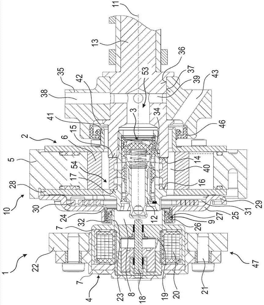
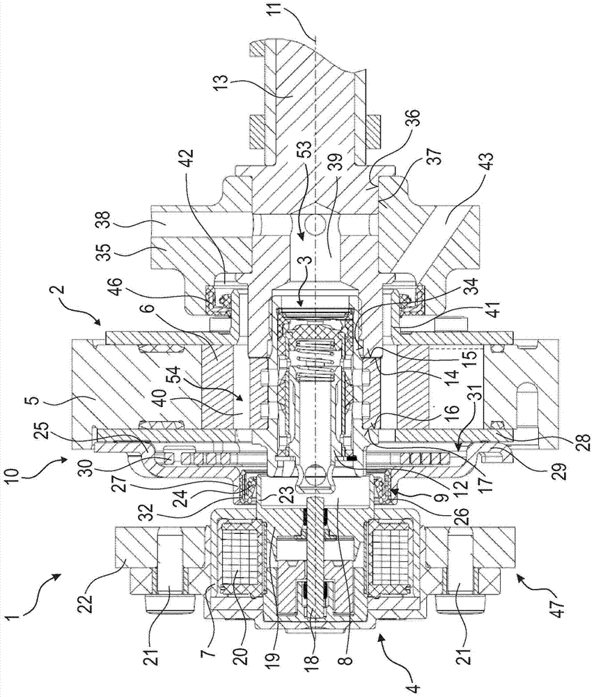
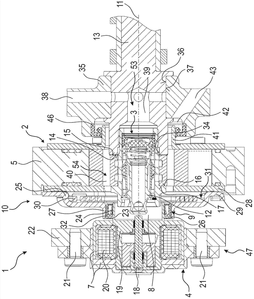
[0060] exist Figure 1 to Figure 16 There are different embodiments of the assembly 1 according to the invention, which can also be referred to as a camshaft adjustment assembly, a camshaft adjustment device or a camshaft adjustment system. In all these figures, the assembly 1 is shown in longitudinal section, wherein an axis of rotation 11 of the assembly lies in the cutting plane, about which the assembly rotates, at least in the operating state. The assembly 1 can be installed in the drive system of a motor vehicle (eg passenger car, van or bus) and can be connected to the camshaft 13 and the crankshaft of an internal combustion engine (eg gasoline or diesel engine). The assembly 1 comprises a camshaft adjuster 2 which is basically constructed and operated according to a camshaft adjuster / device (as it is known from WO 03 / 085238 A1) for varying the control timing of the gas exchange valves of an internal combustion engine . A camshaft adjuster 2 of the type according to t...


PUM


Abstract

The invention relates to an assembly (1) with a vane-type camshaft adjuster (2) and an adjustment actuator (4). A centre valve (3) filled with a fluid for distributing the pressure, such as oil, is arranged in the vane-type camshaft adjuster. The adjustment actuator acts onto the center valve (3) through controlling the pressure fluid. The camshaft adjuster (2) is driven by dry a belt-type transmission element and is provided with a stator (5) and a rotor (6). The pressure fluid is filled in a pressure fluid distributing chamber (8) through the centre valve (3). At least one pressure fluid return pipeline (40) is arranged in the rotor (6). The pressure fluid return pipeline (40) is extending substantially in the axial direction. The invention further relates to a drive system for vehicles.

Description

technical field [0001] The invention relates to an assembly with a vane camshaft adjuster and an adjusting actuator of the type, for example an electrically operable central magnet actuator, wherein there is a central valve distributing a pressurized fluid, such as oil, in the vane camshaft adjuster; The control actuator acts on the central valve in a controlled manner to distribute the pressurized fluid, wherein the camshaft adjuster is driven or can be driven by means of a dry-running traction drive, for example by means of a belt, and has a stator and is rotatably mounted on The rotor therein, and wherein there is a pressurized fluid distribution chamber which can be filled with pressurized fluid through a central valve and at least one pressurized fluid return line is installed in the rotor, the invention also relates to a drive system for a motor vehicle having This assembly, the camshaft connected to the rotor of the camshaft adjuster at least in the operating state, and...

Claims


Application Information

Patent Timeline
IPC IPC(8): F01L1/344
CPCF01L1/024F01L1/3442F01L2001/34423F01L2001/34426
Inventor 阿里·巴伊拉克达尔约阿希姆·迪茨
Owner SCHAEFFLER TECH AG & CO KG
Why Eureka
Try Eureka