Water pan and air energy water heater with same

An air-energy water heater and water-receiving pan technology, which is applied to fluid heaters, lighting and heating equipment, etc., can solve the problems of poor drainage, difficult drainage, and the inability of the heat pump to operate reliably, and achieve the effect of draining condensate water well.

Inactive Publication Date: 2015-01-14
GREE ELECTRIC APPLIANCES INC
View PDF7 Cites 1 Cited by
  • Summary
  • Abstract
  • Description
  • Claims
  • Application Information

AI Technical Summary

Problems solved by technology

On the other hand, in the low temperature environment of the condensate drainage structure, the condensate generated by the operation of the heat pump will freeze at the condensate drain hole due to poor drainage and difficult drainage, resulting in ice blockage and the condensate cannot be discharged, making the heat pump unreliable operation, challenging to operate reliably in heat pump mode

Method used


Image

  • Water pan and air energy water heater with same
  • Water pan and air energy water heater with same

Examples


no. 1 example

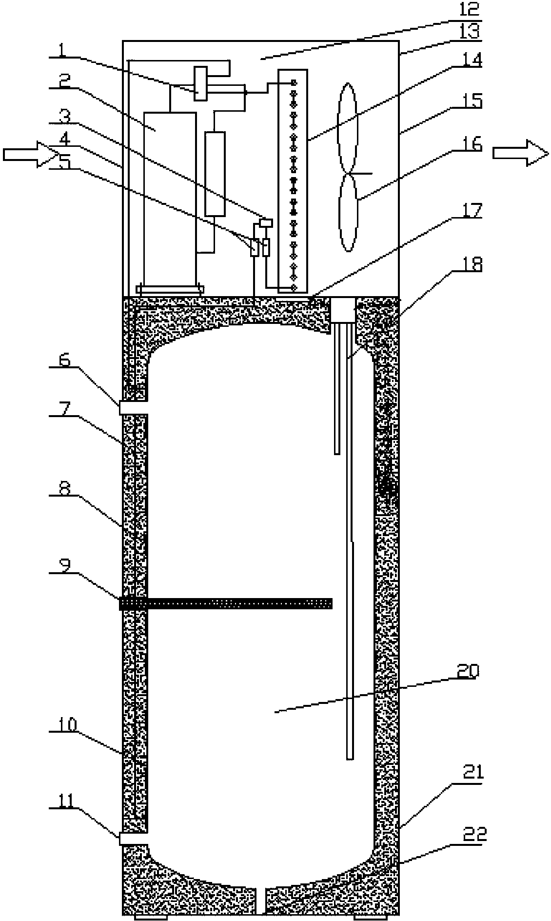
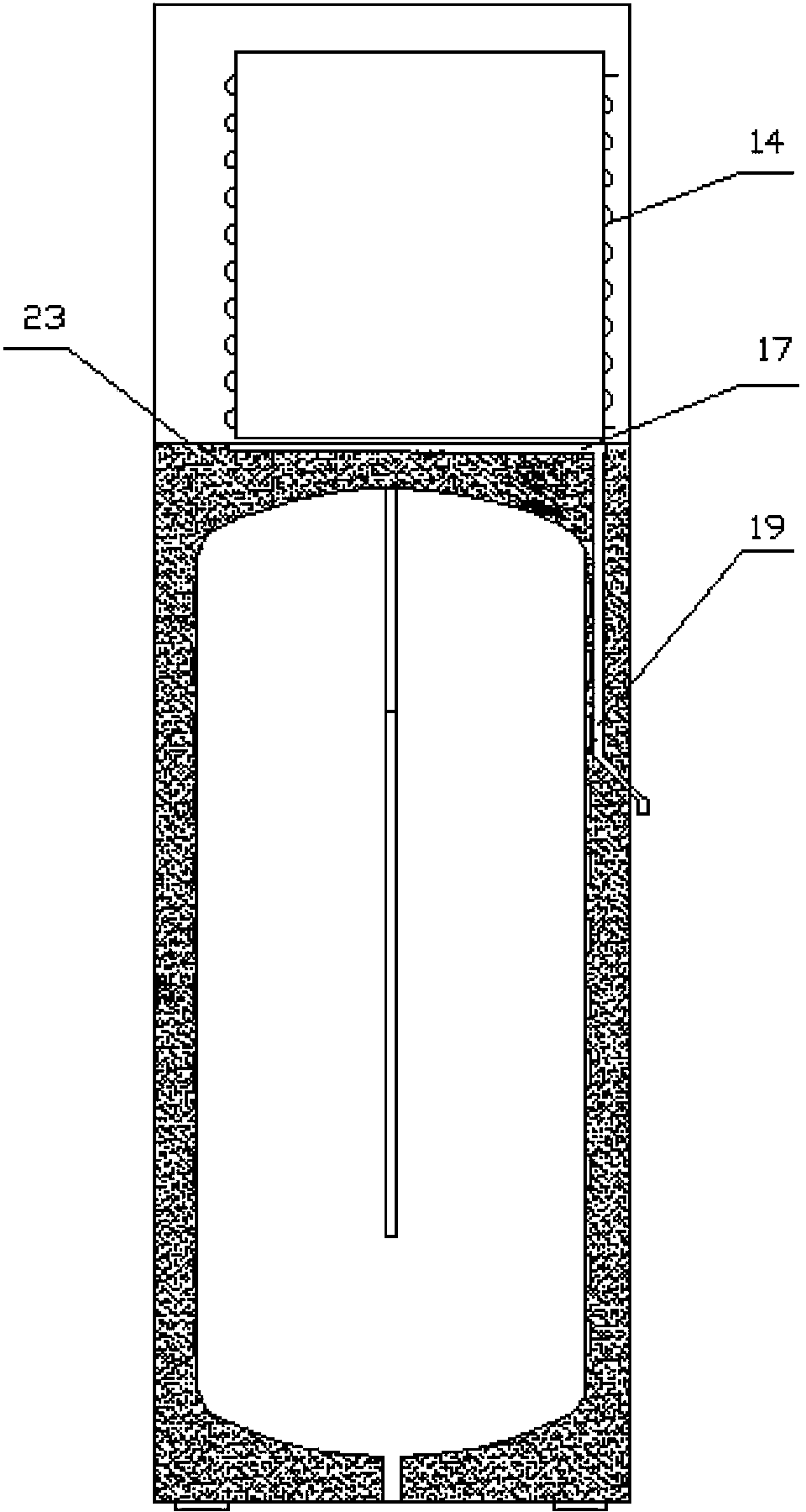
[0024] Taking the integral air energy water heater as an example, the present invention provides the first embodiment of the integral air energy water heater, for details, refer to figure 1 , figure 2 , the integrated air energy water heater of the present invention includes an external machine part 12 and a water tank part 20, and the external machine part 12 includes a working medium reversing element 1, a compressor 2, a throttling element 3, an air inlet 4, and a filter 5, Outer cover 13, external machine heat exchanger 14, air outlet 15, fan system 16, water receiving tray 17. The water tank component 20 includes a water outlet 6, an insulation layer 7, a water tank heat exchanger 8, a magnesium rod 9, an inner tank 10, a water inlet 11, a temperature sensing package 18, a drain pipe 19, a casing 21, a sewage outlet 22, and a chassis 23 .

[0025] Preferably, the water receiving tray 17 includes a water receiving surface and a bottom surface, and the water receiving su...


PUM


Abstract

The invention discloses a water pan which comprises a water receiving face and a bottom face. The included angle formed between the water receiving face and the horizontal plane ranges from 1 degree to 60 degrees. The tilt design of the water pan conforms to the water flow direction, and condensate water is better drained. The invention further provides an air energy water heater with the water pan. A drainage pipe is arranged between an inner container and a heat preservation layer, the outlet water temperature of the condensate water is increased, and the problem of ice blockage of the condensate water is solved at low temperature.

Description

technical field [0001] The invention relates to the field of air energy water heaters, in particular to a water receiving tray for air energy water heaters. Background technique [0002] The drainage structure of the condensed water of the household integrated air source water heater, in which the water receiving tray is generally arranged horizontally to collect the condensed water generated by the heat exchanger, and the condensed water drainage hole is directly opened on the side of the chassis of the external machine components to discharge the water directly. With this design, on the one hand, when the condensed water is discharged, because the water receiving pan is arranged horizontally, the condensed water cannot be completely discharged to the outside, and a lot of condensed water still accumulates in the water receiving pan. On the other hand, in the low temperature environment of the condensate drainage structure, the condensate generated by the heat pump operatio...

Claims


Application Information

Patent Timeline
Patent Type & Authority Applications(China)
IPC IPC(8): F24H9/16F24H4/02
Inventor 邓伟彬
Owner GREE ELECTRIC APPLIANCES INC
Why Eureka
Try Eureka