Method for designing transmitting directional diagram of foresight airborne radar

A technology of emission pattern and airborne radar, applied in the field of radar, can solve the problems of poor adaptability, low signal-to-noise ratio of target echo, strong radiation energy, etc., to suppress clutter, improve adaptability, and reduce radiation energy Effect

Active Publication Date: 2015-01-14
XIDIAN UNIV
View PDF3 Cites 9 Cited by
  • Summary
  • Abstract
  • Description
  • Claims
  • Application Information

AI Technical Summary

Problems solved by technology

In order to solve the problem of poor adaptability of traditional airborne radar transmitter design, strong ra

Method used


Image

  • Method for designing transmitting directional diagram of foresight airborne radar
  • Method for designing transmitting directional diagram of foresight airborne radar
  • Method for designing transmitting directional diagram of foresight airborne radar

Examples


Embodiment Construction

[0034] The present invention will be further described below in conjunction with accompanying drawing:

[0035] The array elements of the forward-looking airborne radar targeted by the present invention present an equidistant distribution, the number of array elements of the airborne radar is N, the distance between adjacent array elements of the airborne radar is d, and the working wavelength of the airborne radar is λ. The number of pulses transmitted by the radar is M, and the pitch angle of the aircraft is Carrier speed v.

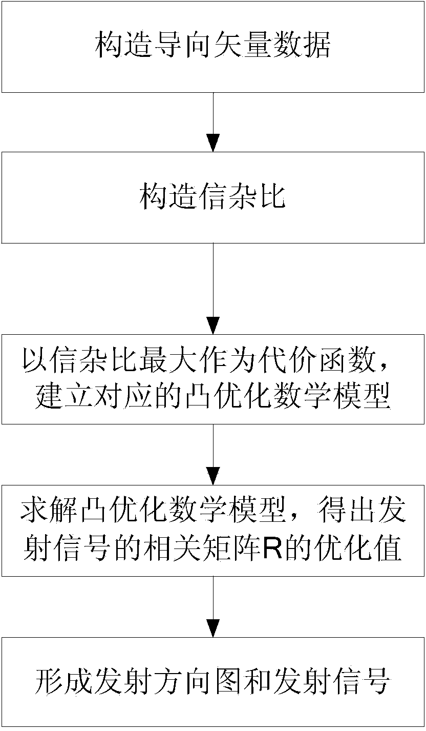
[0036] refer to figure 1 , for the forward-looking airborne radar transmission pattern design method of the present invention, may further comprise the steps:

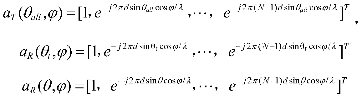
[0037] Step 1: Use the echo information at the previous moment to construct the steering vector at the current moment.

[0038] 1a) Extract the azimuth angle θ of the target from the echo signal received by the forward-looking airborne radar at the last moment t , the azimuth angle θ of the ...


PUM


Abstract

The invention discloses a method for designing a transmitting directional diagram of foresight airborne radar. The problems that a designed directional diagram is poor in self adaptability in the prior art, radiation energy in a clutter area is high and the target echo signal-to-clutter ratio is low are mainly solved. The method includes the implantation steps that first, steering vectors are constructed according to target echo signals and clutter echo signals received by the airborne radar at the previous moment and foresight airborne radar parameters; second, the target echo and the clutter echo are calculated according to the steering vectors, so that a target signal average power formula and a clutter signal average power formula are obtained; third, the signal-to-clutter ratio is constructed through the target signal average power and the clutter signal average power; fourth, the maximum signal-to-clutter ratio is used as a cost function, so that a corresponding convex optimized mathematical model is established, and the optimum value of a transmitting signal correlation matrix is obtained; fifth, the transmitting directional diagram of the foresight airborne radar is figured out. The designed transmitting directional diagram can generate a low side lobe in a high clutter area, the radiation energy in the high clutter area can be lowered, and the method can be used for improving the clutter inhibiting capacity of a transmitting terminal.

Description

technical field [0001] The invention belongs to the technical field of radar and relates to suppression of clutter at an airborne transmitter, in particular to a method for designing an airborne radar transmission pattern, which is used to improve the suppression capability of clutter. Background technique [0002] The widespread application of digital components in radar systems has produced digital array radars, and each array element of digital array radars can emit different signals. The concept of MIMO in the field of simultaneous communication[Rabideau D.J.and Parker P..Ubiquitous MIMO Multifunction Digital Array Radar[C].Conference Record of the 37th Asilomar Conference on Signals,Systems and Computers,2003,vol.1,pp.1057-1064 ] and technology and the application of SIAR in radar, making the digital array radar come into play. MIMO radars can be divided into distributed MIMO radars and centralized MIMO radars according to the distance between the transmitting and rece...

Claims


Application Information

Patent Timeline
IPC IPC(8): G01S7/28G01S7/282
CPCG01S7/282
Inventor 左群声刘宏伟施君南纠博王英华戴奉周
Owner XIDIAN UNIV
Why Eureka
Try Eureka