Supercharge Your Innovation With Domain-Expert AI Agents!

Power modeling method for numerical control machine tool system

A technology of numerical control machine tool and modeling method, which is applied in the direction of general control system, control/regulation system, digital control, etc., and can solve problems such as ignoring the power loss of the feed system, complex and changeable processing technology, and no power model of the numerical control machine tool system.

Inactive Publication Date: 2015-01-14
HUAZHONG UNIV OF SCI & TECH
View PDF7 Cites 23 Cited by
  • Summary
  • Abstract
  • Description
  • Claims
  • Application Information

AI Technical Summary

Problems solved by technology

However, it is very difficult to obtain these parameters at the production site. In addition, this detection method completely ignores the power loss of the feed system
[0006] In short, due to the many energy-consuming links of the machine tool, the complex and changeable processing technology, and the frequent changes in the types of tools and blanks, the energy flow of the CNC machine tool system is very complicated. In addition, the electromagnetic loss is large, and the tool is dynamically worn during the machining process. The CNC machine tool system still does not have a reasonable power model

Method used


Image

  • Power modeling method for numerical control machine tool system
  • Power modeling method for numerical control machine tool system
  • Power modeling method for numerical control machine tool system

Examples


Embodiment Construction

[0042] In order to make the object, technical solution and advantages of the present invention clearer, the present invention will be further described in detail below in conjunction with the accompanying drawings and embodiments. It should be understood that the specific embodiments described here are only used to explain the present invention, not to limit the present invention. In addition, the technical features involved in the various embodiments of the present invention described below can be combined with each other as long as they do not constitute a conflict with each other.

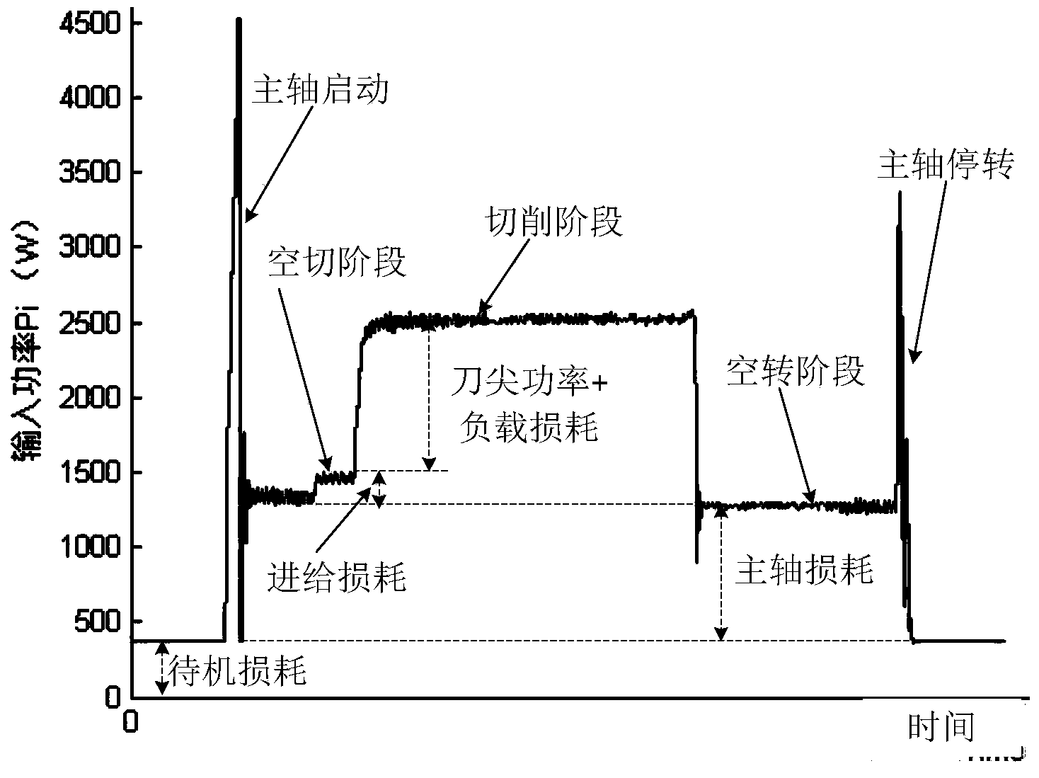
[0043] The power modeling method of the numerical control machine tool system of the present invention comprises:

[0044] The CNC machine tool system is divided into four states: standby, idling, air cutting and cutting, among which,

[0045] The standby state is the working state of only the auxiliary system of the CNC machine tool system, and the auxiliary system includes a control system, a...


PUM


Abstract

The invention discloses a power modeling method for a numerical control machine tool system. The four states of the numerical control machine tool system include the stand-by state, the idle state, the air cutting state and the cutting state. The power P<spindle>, needing to be increased, of the numerical control machine tool system in the idle state relative to the stand-by state, the power P<feed>, needing to be increased, of the numerical control machine tool system in the air cutting state relative to the idle state, and the power P<tip> and P<add>, needing to be increased, of the numerical control machine tool system in the cutting state relative to the air cutting state are obtained, and a power model of the numerical control machine tool system is the sum of the power P<0> in the stand-by state, the P<spindle>, the P<feed>, the P<tip> and the P<add>. The power model built with the power modeling method is clear in physical significance, reasonable, simple and accurate.

Description

technical field [0001] The invention belongs to the field of energy consumption of numerical control machine tools, and more specifically relates to a power modeling method of a numerical control machine tool system. Background technique [0002] China Statistical Yearbook shows that in 2012 China consumed 3,617.32 million tons of standard coal, and its CO2 emissions reached 795.41 million tons, of which manufacturing energy consumption accounted for more than 50% of the country's total energy consumption. Facing increasingly stringent environmental legislation and high resource costs, the manufacturing industry is under tremendous pressure to reduce energy consumption and carbon emissions. my country's manufacturing industry has a large number of machine tools. The total installed power of existing machine tools is about 80 million kilowatts. The energy demand is huge, but its energy utilization rate is very low. There is huge potential and broad space for energy saving and...

Claims


Application Information

Patent Timeline
Patent Type & Authority Applications(China)
IPC IPC(8): G05B19/18
CPCG05B19/41885
Inventor 黄拯滔邵新宇张超勇罗敏毛新勇刘红奇谢阳周志恒
Owner HUAZHONG UNIV OF SCI & TECH
Features
  • R&D
  • Intellectual Property
  • Life Sciences
  • Materials
  • Tech Scout
  • Unparalleled Data Quality
  • Higher Quality Content
  • 60% Fewer Hallucinations
Learn More