Heat-exchanger header and heat exchanger provided therewith
A technology of heat exchanger and heat exchange part, applied in the direction of heat exchange equipment, heat exchanger type, heat exchanger shell, etc., can solve the problems of distributing refrigerant, performance degradation of heat exchanger, etc., to achieve equal structure, pressure loss inhibiting effect
- Summary
- Abstract
- Description
- Claims
- Application Information
AI Technical Summary
Problems solved by technology
Method used
Image

Examples
Embodiment approach 1
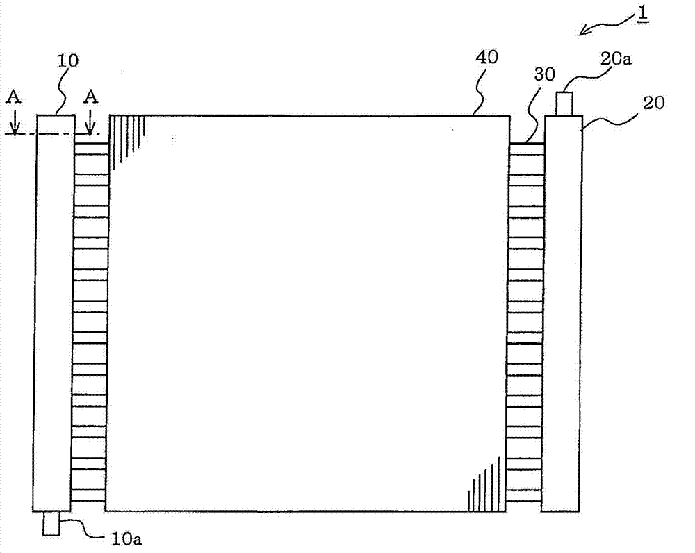
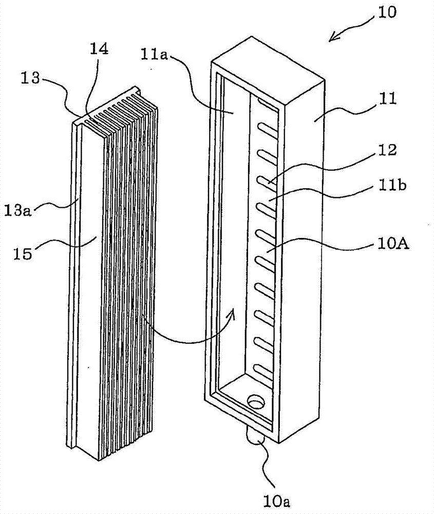
[0034] figure 1 It is a schematic perspective view of a heat exchanger using the heat exchanger header according to Embodiment 1 of the present invention. exist figure 1 As well as in the drawings described later, members assigned the same reference numerals are the same or equivalent members, and this applies throughout the specification. In addition, the form of the component shown in the whole specification is a mere illustration, and is not limited to these descriptions.
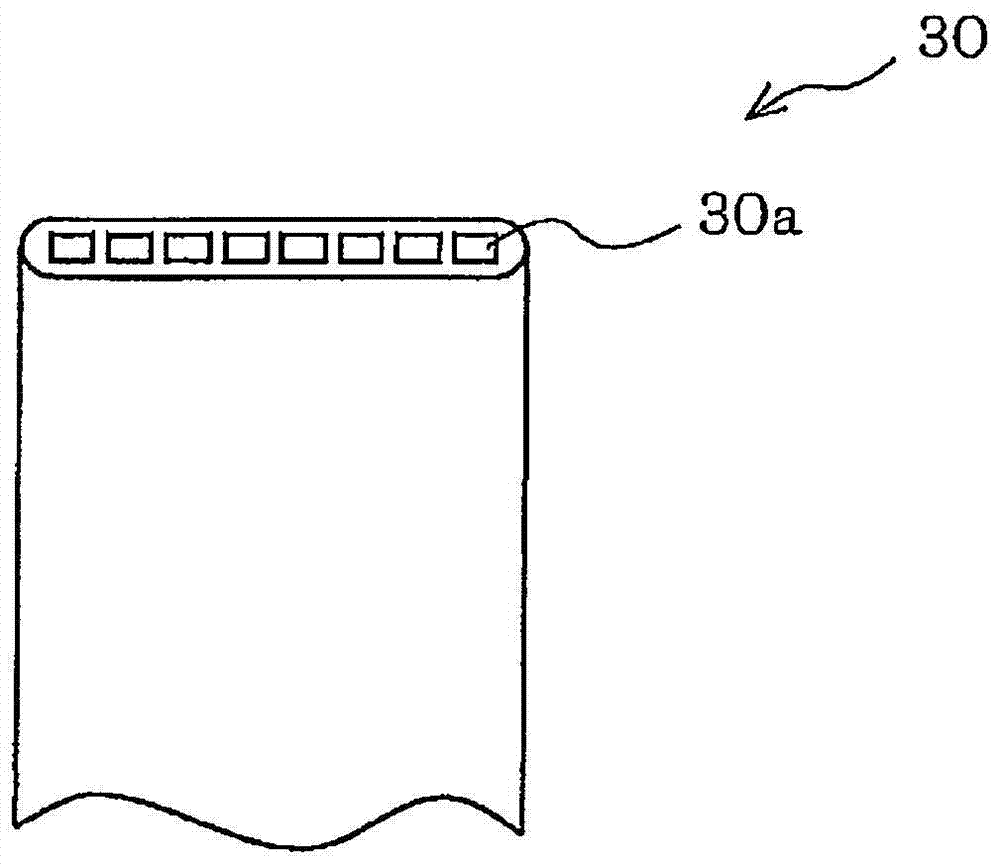
[0035] The heat exchanger 1 is a parallel-flow heat exchanger in which refrigerant flows in parallel, and in particular, is a unidirectional flow-path type heat exchanger in which refrigerant flows from one side to the other in the entire heat exchanger 1 . The heat exchanger 1 includes a pair of headers 10, 20 arranged apart from each other; a plurality of flat tubes ( heat transfer tubes) 30; and a plurality of fins 40. A pair of header pipes 10, 20, flat tubes 30, and fins 40 are all made of alumi...
Embodiment approach 2
[0062] Figure 12 It is a figure which shows 1 A of heat exchangers concerning Embodiment 2 of this invention.
[0063] The heat exchanger 1A is a parallel-flow heat exchanger that makes refrigerant flow in parallel, and is particularly a reentrant flow path type heat exchanger. In addition, a configuration example in which the number of paths is five is shown here.
[0064] The heat exchanger 1A includes a pair of headers 70, 80 arranged away from each other; a plurality of headers (here, 20) flat tubes (heat transfer tubes) 30; and a plurality of fins 40. The pair of headers 70 and 80, the flat tube 30, and the fins 40 are all made of aluminum or an aluminum alloy. The structures of the flat tubes 30 and the fins 40 are the same as those of the first embodiment.
[0065] Figure 13 yes figure 1 An exploded perspective view of header 70 of FIG.
[0066] The header 70 has a box-shaped header body 71 with one surface open. On the bottom surface 71b of the header main bo...
Embodiment approach 3
[0082] Embodiment 3 corresponds to the structure in which the return flow path type heat exchangers of Embodiment 2 are provided in multiple rows (here, two rows) in the air passing direction.
[0083] Figure 15 It is a figure which shows the heat exchanger of Embodiment 3 of this invention. Figure 15 (a) is a schematic side view of the heat exchanger viewed from a direction perpendicular to the air passage direction indicated by the dotted line arrow. Figure 15 (b) is a schematic cross-sectional view of the upstream side heat exchange part 1Ba on the upstream side with respect to the air passing direction. Figure 15 (c) is a schematic cross-sectional view of the downstream side heat exchange part 1Bb on the downstream side with respect to the air passing direction. Figure 15 (d) is a plan view of the heat exchanger. Hereinafter, the differences between Embodiment 3 and Embodiment 2 will be mainly described.
[0084] The heat exchanger 1B includes the same heat exchan...
PUM
 Abstract
Description
Claims
Application Information
 - R&D
- Intellectual Property
- Life Sciences
- Materials
- Tech Scout
- Unparalleled Data Quality
- Higher Quality Content
- 60% Fewer Hallucinations
Browse by: Latest US Patents, China's latest patents, Technical Efficacy Thesaurus, Application Domain, Technology Topic, Popular Technical Reports.
© 2025 PatSnap. All rights reserved.Legal|Privacy policy|Modern Slavery Act Transparency Statement|Sitemap|About US| Contact US: help@patsnap.com