Vibrated fluidized bed electric separator

A technology of vibrating fluidized bed and electric separator, applied in electrostatic effect separation, chemical instruments and methods, solid separation, etc., can solve the problems of poor separation of fine-grained minerals and limited application range, etc. Wide range of well-designed effects

Inactive Publication Date:
View PDF9 Cites 10 Cited by
  • Summary
  • Abstract
  • Description
  • Claims
  • Application Information

AI Technical Summary

Problems solved by technology

[0004] The purpose of the present invention is to provide a vibrating fluidized bed electric separator for the above-mentioned problems in the prior art, which solves the technical problems in the prior art that the separation effect of fine-grained minerals is not good and the scope of application is not wide

Method used


Image

  • Vibrated fluidized bed electric separator

Examples


Embodiment Construction

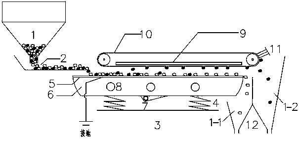
[0017] The present invention will be further described below with reference to specific embodiments and accompanying drawings.

[0018] like figure 1 As shown, a vibrating fluidized bed electrical separator includes a material buffer bin 1, a feeding device 2, a base 3, a vibrating fluidized bed, a high-voltage electrode plate 9, a non-conductor belt 10 and a material collection device 12. The silo 1 is installed above the feeding device 2. The vibrating fluidized bed includes a vibration exciter 7, an air distribution chamber 6 and a conductive air distribution plate 5. The conductive air distribution plate 5 constitutes the conductive working surface of the vibrating fluidized bed. The conductive air distribution plate 5 is sealed and fixed above the air distribution chamber 6 through insulating materials, provides a constant airflow into the air distribution chamber 6 through the air inlet 8, and forms an upward airflow through the conductive air distribution plate 5, and t...


PUM


Abstract

The invention discloses a vibrated fluidized bed electric separator which comprises a feed device, a base, a vibrated fluidized bed, a high-voltage electrode plate, a non-conductor belt and a material collection device. The vibrated fluidized bed is arranged on the base by virtue of a spring; the conductive working surface of the vibrated fluidized bed is earthed, and the non-conductor belt which externally wraps the high-voltage electrode plate is arranged above the working surface; the high-voltage electrode plate and the working surface are arranged in parallel and are connected with a high-voltage power source by virtue of a wire; the feed device is arranged on one end of the vibrated fluidized bed while the material collection device is arranged on the other end thereof; the material collection device comprises an ore concentrate groove and a tailing groove; the tailing groove is arranged near the vibrated fluidized bed; the ore concentrate groove is arranged by corresponding to the end part of the non-conductor belt. The vibrated fluidized bed electric separator is reasonable in design and wide in application range and can separate any mineral; the electric separator is particularly suitable for size fraction ranging from -1 mm to 0.2 mm and can perform continuous flow state separation and production to obtain target minerals in higher quality.

Description

technical field [0001] The invention belongs to the field of electro-separator and mineral electro-separation, in particular, for -1mm-0.2mm particle size, the electro-separation method is used to carry out continuous fluidized separation and production, so as to obtain the dry separation equipment of higher-grade target minerals. . Background technique [0002] With the increase of human demand for mineral resources, the ore of newly mined mines has the trend of "poor", "fine" and "miscellaneous", and these characteristics are more obvious in China. At present, the development and utilization of mineral resources in my country are mainly concentrated in the eastern region, and most of the traditional process methods use wet separation technology for separation. The western region is dry and water-deficient, so the development of high-efficiency dry mineral processing equipment and supporting technology is of great significance to the utilization of the rich mineral resourc...

Claims


Application Information

Patent Timeline
Patent Type & Authority Applications(China)
IPC IPC(8): B03C7/08
Inventor 何亚民魏勇徐智平
Why Eureka
Try Eureka