Anti-thunder detection automatic wind-up device

A wire take-up device and automatic detection technology, which is applied in the field of wire take-ups, can solve problems such as unsuitable for lightning protection detection work, automatic shutdown without setting, and foreign objects on the line without setting, so as to improve the efficiency of lightning protection detection and change time-consuming Effortless, easy-to-carry effect

Inactive Publication Date: 2015-01-21
北京市避雷装置安全检测中心
View PDF5 Cites 1 Cited by
  • Summary
  • Abstract
  • Description
  • Claims
  • Application Information

AI Technical Summary

Problems solved by technology

[0003] Manual winding has the following disadvantages: 1. Manual winding one by one, the winding speed is slow, which affects the work efficiency
[0004] At present, there are automatic wire take-up machines used by cable manufacturers in terms of wire take-ups, which need to be driven by a large motor, and need a matching polished rod wire arrangement (which also requires power). The wire take-up machine used is heavy and inconvenient to carry around. Generally, there is no solution for the line being stuck by foreign objects, so it is not suitable for use in lightning protection detection work; the kite automatic wire take-up is also not equipped with a method for automatically stopping when the line is stuck by foreign objects, and there is no discharge The seam makes the thread have a guiding effect and the thread can be taken up smoothly; when the earphone line or the hair dryer line is automatically taken up, the vortex spring or clockwork is generally used. Since the test line used for the lightning protection test is long, the force required to take it up Larger, it is difficult to use a vortex spring or spring, so it is necessary to design an automatic wire take-up for the needs of lightning protection detection work

Method used


Image

  • Anti-thunder detection automatic wind-up device
  • Anti-thunder detection automatic wind-up device
  • Anti-thunder detection automatic wind-up device

Examples


Embodiment Construction

[0026] The present invention will be described in further detail below in conjunction with the accompanying drawings and embodiments.

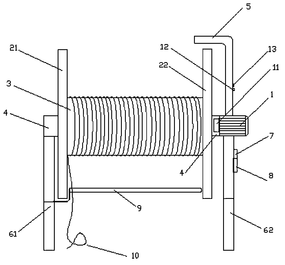
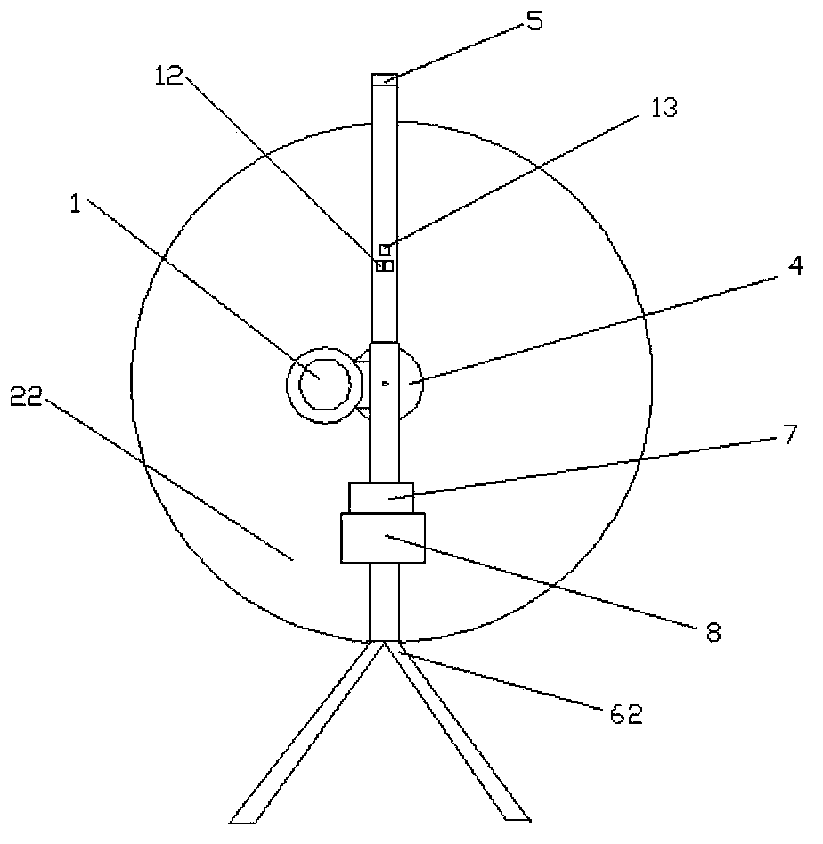
[0027] An automatic take-up device, such as figure 1 Said, including the first support 61, the second support 62, between the first support 61 and the second support 62, the take-up reel 3 and the take-up reel rotating shaft 4 are housed; A wire blocking plate 21 and a second wire blocking plate 22 . The motor 1 is fixed on the second bracket 62, and the take-up spool rotating shaft 4 and the motor rotating shaft 11 are connected together to form an integral body through a gear connection, wherein a PLC integrated circuit box 7 is also installed on the second bracket 62, and the PLC integrated The circuit box 7 is electrically connected to the motor 1 .

[0028] In lightning protection testing, many on-site environments are relatively complex, and there are many other equipment on site (such as fans on the roof, outdoor units of air conditio...


PUM


Abstract

The invention relates to a wind-up machine, in particular to an anti-thunder detection automatic wind-up device. The anti-thunder detection automatic wind-up device comprises a first support, a second support, a wind-up cylinder and a wind-up cylinder rotating shaft; the wind-up cylinder and the wind-up cylinder rotating shaft are arranged between the first support and the second support; a first wire blocking plate and a second wire blocking plate are fixed to the two ends of the wind-up cylinder respectively. A winding displacement gap for guiding test wires is formed in the first support. A motor is fixed to the second support; the wind-up cylinder rotating shaft and a motor rotating shaft are connected through a gear and are jointly formed into a whole. A PLC integrated circuit box is arranged on the support, is in circuit connection with the motor and is used for enabling the motor to immediately stop from rotating when the test wires are clamped in a certain position of the scene, and the phenomenon that the wires are pulled apart or the motor is overheated to be damaged is avoided. According to the device, labor intensity of detection personnel is reduced, the situation that labor is wasted in the manual wind-up process is changed, wind-up and paying off can be rapidly achieved, and meanwhile the wound wires are in order and are prevented from being disordered.

Description

technical field [0001] The invention relates to a wire take-up device, in particular to an automatic wire take-up device for lightning protection detection. Background technique [0002] One of the important tasks in the lightning protection detection process is to measure the grounding resistance of the lightning protection device or the equipotential transition resistance between other equipment and the lightning protection device, so as to judge whether the lightning protection is qualified. In the above two measurements, it is necessary to pull a special test line. Usually, it needs to be taken up and then released from one platform on the roof to another platform. Even on the same larger roof platform, the line needs to be taken up and released. Take-up and pay-off are very frequent. In addition, the test lines used in some testing places are very long. For example, in the lightning protection detection of subway stations, the current extreme test line is about 200 met...

Claims


Application Information

Patent Timeline
IPC IPC(8): B65H75/38B65H75/44B65H75/48
Inventor 李京校宋平健宋海岩李如箭逯曦张宇龙
Owner 北京市避雷装置安全检测中心
Why Eureka
Try Eureka