
Loading mechanism adopting MDOF (multiple degree of freedom) controllable connecting rods

A loading mechanism and degree-of-freedom technology, applied in mechanically driven excavators/dredgers, etc., can solve the problems of insensitive response, high maintenance costs, and large connecting rod transmission parts, so as to simplify the connecting rod transmission part, reduce the The labor intensity of workers and the effect of flexible and changeable driving methods

Inactive Publication Date: 2015-01-21
GUANGXI UNIV
View PDF6 Cites 15 Cited by
  • Summary
  • Abstract
  • Description
  • Claims
  • Application Information

AI Technical Summary

Problems solved by technology

[0005] The purpose of the present invention is to provide a multi-degree-of-freedom controllable connecting rod loading mechanism, which should firstly have the advantages of large working space, large loading force, and good force bearing of traditional hydraulic loaders, and overcome the high maintenance cost of traditional hydraulic loaders and the difficulty of operation. It has the disadvantages of high noise, high cost of hydraulic components, and insufficient response. At the same time, it solves the shortcomings of other controllable loading mechanisms, small working space of electric loading mechanisms, large connecting rod transmission parts, complicated mechanisms, and difficulty in ensuring the force of each connecting rod. place

Method used


Image

  • Loading mechanism adopting MDOF (multiple degree of freedom) controllable connecting rods
  • Loading mechanism adopting MDOF (multiple degree of freedom) controllable connecting rods
  • Loading mechanism adopting MDOF (multiple degree of freedom) controllable connecting rods

Examples


Embodiment Construction

[0019] The technical solutions of the present invention will be further described below through the accompanying drawings and embodiments.

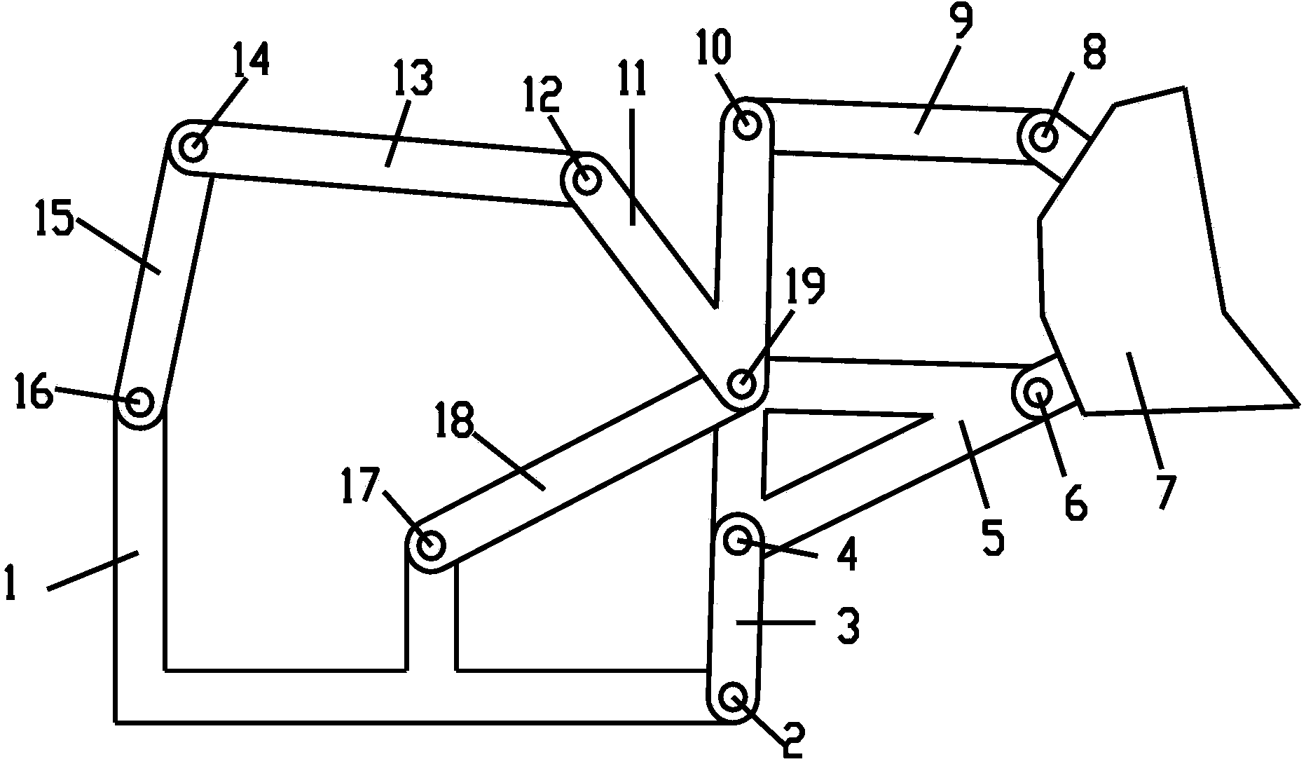
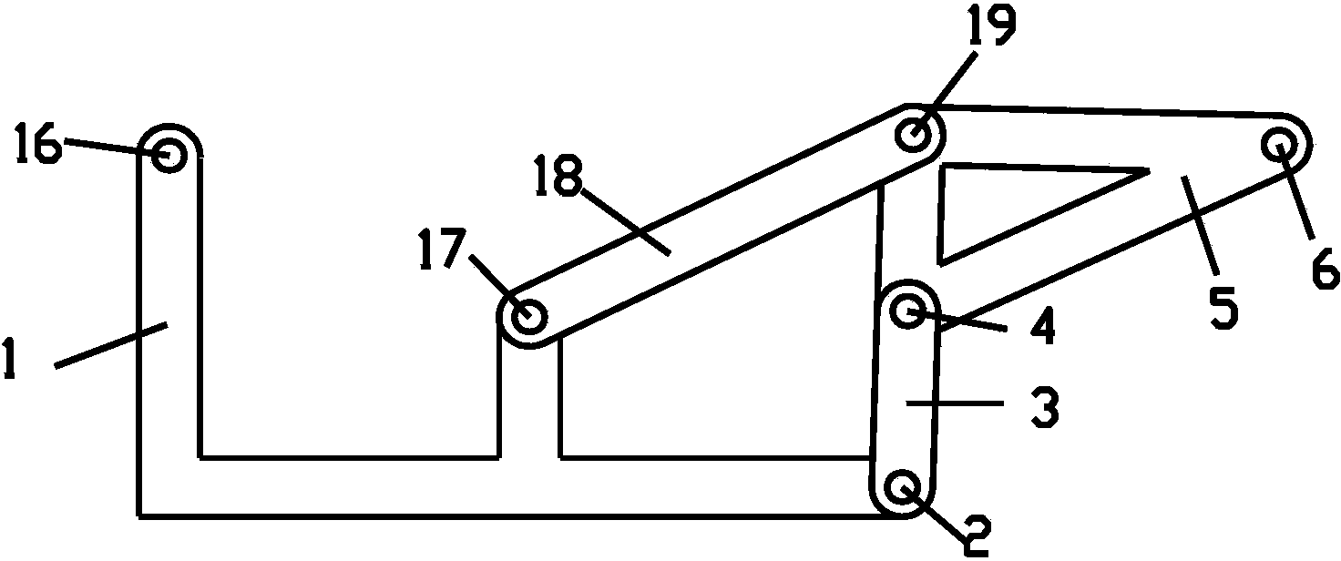
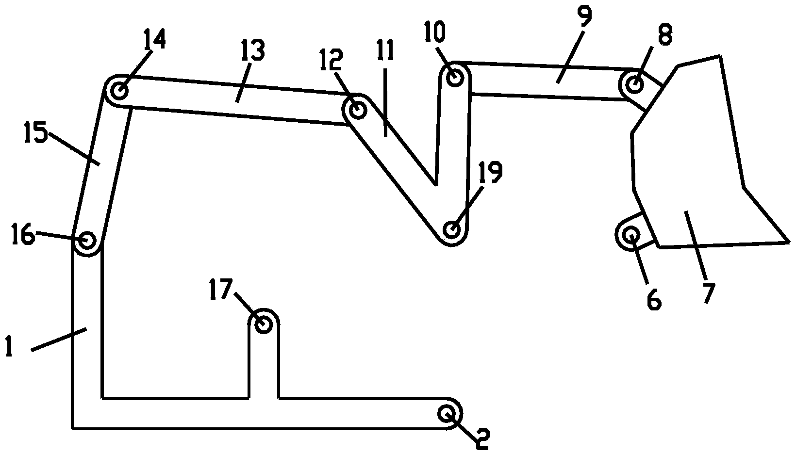
[0020] like Figure 1-Figure 5 As shown, a multi-degree-of-freedom controllable link loading mechanism includes a frame 1, a lifting mechanism and a bucket turning mechanism;

[0021] The lifting mechanism includes a second active rod 18, a third connecting rod 3 and a first support frame 5. One end of the second active rod 18 is connected to the frame 1 through the second rotating pair 17, and the other end is connected to the frame 1 through the third rotating pair. 19 is connected to the first end of the first support frame 5; one end of the third link 3 is connected to the frame 1 through the tenth rotating pair 2, and the other end is connected to the second end of the first supporting frame 5 through the first rotating pair 4. End connection, the third end of the first support frame 5 is connected with the bucket 7 through the four...


PUM


Abstract

The invention discloses a loading mechanism adopting MDOF (multiple degree of freedom) controllable connecting rods. Two ends of a second driving lever of a lifting mechanism are connected with a stander and a first end of a first support frame respectively; two ends of a third connecting rod are connected with the stander and a second end of the first support frame, and a third end of the first support frame is connected with a bucket; two ends of a first driving lever of a bucket turnover mechanism are connected with the stander and one end of a first connecting rod respectively, the other end of the first connecting rod is connected with a first end of a second support frame, a second end of the second support frame is connected with one end of the a second connecting rod, a third end of the second support frame is connected with the second driving lever, and the other end of the second connecting rod is connected with the bucket. The loading mechanism can solve the defects that a traditional hydraulic loading machine is complicated in system, easy to leak oil, high in machining precision requirement and the like, and has the advantages of an MDOF controllable mechanism type loading machine, such as flexibility, rapid action and the like; moreover, a connecting rod transmission part is more simple, each rod and each joint bear force batter, and a work space is larger, so that the loading mechanism is more suitable for manufacturing various loading machines and other engineering machinery.

Description

technical field [0001] The invention relates to the field of engineering machinery, in particular to a multi-degree-of-freedom controllable link loading mechanism. Background technique [0002] In the field of construction machinery today, loaders are one of the most important construction machinery, and most of the current loaders are full hydraulic full-slewing loaders. The full hydraulic loader is also undergoing continuous improvement and innovation of control methods, so that the loader has developed from simple lever control to hydraulic control, pneumatic control, hydraulic servo control and electrical control, radio remote control, and computer integrated program control. However, hydraulic loaders also have many deficiencies and shortcomings. First, hydraulic components require high machining accuracy, high cost, strict assembly requirements, difficult manufacturing, and high technical and difficult maintenance requirements during use; secondly, hydraulic oil is aff...

Claims


Application Information

Patent Timeline
Patent Type & Authority Applications(China)
IPC IPC(8): E02F3/38
Inventor 蔡敢为王麾张林范雨李智杰朱凯君王龙张永文王小纯杨旭娟李岩舟温芳
Owner GUANGXI UNIV
Learn More