Steel reinforced concrete column-steel reinforced concrete inclined beam T-shaped joint

A technology of concrete columns and concrete beams, which is applied in the direction of architecture and building construction, can solve the problems of high cost, complicated process, poor fire resistance and corrosion resistance, etc., and achieve the effect of strengthening the node area

Inactive Publication Date: 2015-01-21
STATE NUCLEAR ELECTRIC POWER PLANNING DESIGN & RES INST CO LTD +1
View PDF4 Cites 2 Cited by
  • Summary
  • Abstract
  • Description
  • Claims
  • Application Information

AI Technical Summary

Problems solved by technology

[0002] With the development of society, the capacity of nuclear power plant units is increasing. In order to improve the characteristics of high cost, poor fire resistance and corrosion resistance of steel structures, it is necessary to adopt steel concrete frame bent structure. Due to the complex process of the main building of nuclear power plants, in order to meet the Due to the technical and drainage requirements, the structure of the main powerhouse is irregular. In this case, since the beams and columns in the conventional joints are arranged vertically, the limitation of the structure itself makes it unable to meet the above-mentioned main powerhouse requirements although it meets the seismic requirements for both bearing capacity and deformation. Process requirements and drainage requirements for the specific structure of the plant

Method used


Image

  • Steel reinforced concrete column-steel reinforced concrete inclined beam T-shaped joint
  • Steel reinforced concrete column-steel reinforced concrete inclined beam T-shaped joint
  • Steel reinforced concrete column-steel reinforced concrete inclined beam T-shaped joint

Examples


Embodiment

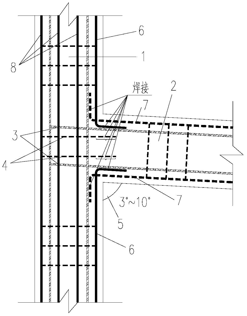
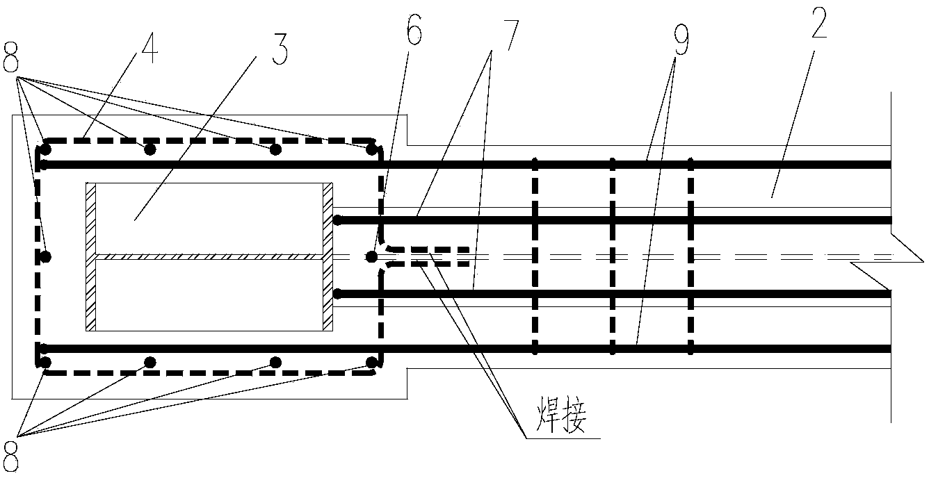
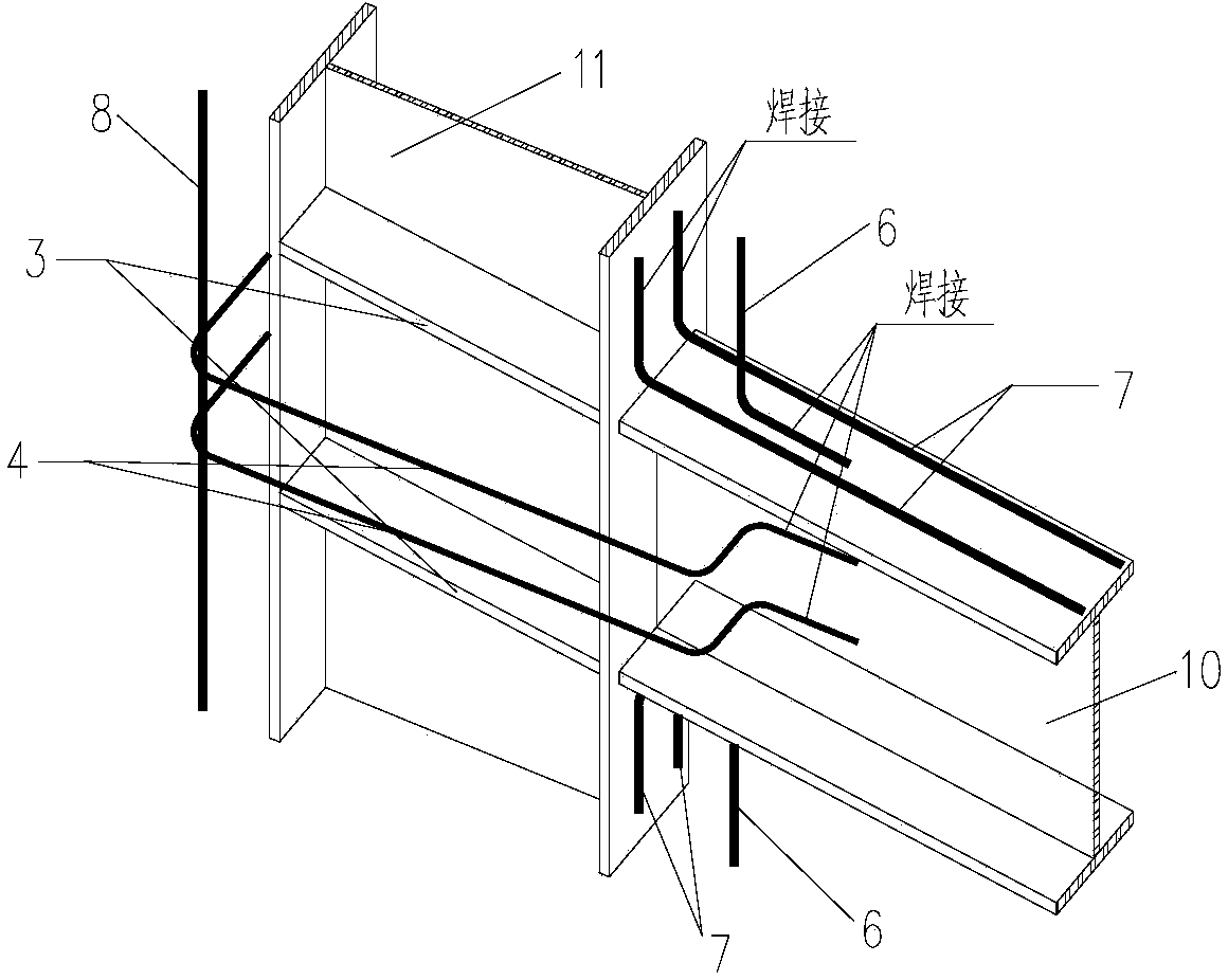
[0027] Following the above-mentioned technical scheme of the present invention, this embodiment provides a steel concrete column-steel concrete oblique beam T-shaped joint, the structure of which is shown in Figure 1 ~ Figure 3 , the node is formed by the solid connection (welding) of steel concrete column 1 and steel concrete beam 2; said steel concrete beam 1 is provided with H-shaped steel 10 in the beam, and said steel concrete column 2 is provided with H-shaped steel 11 in the column ;in:

[0028] Along the upper and lower flanges of the H-shaped steel 10 in the beam, one or more longitudinal ribs 7 in the beam need to pass through the flange of the medium-shaped steel in the column, and one end thereof is bent when reaching the flange of the medium-shaped steel 11 in the column. It is flush with the flange of the column-medium steel 11, and fixed (welded) on the flange of the column-medium-shaped steel 11; in the steel-reinforced concrete beam 1, one or more horizontal...


PUM

PropertyMeasurementUnit
angleaaaaaaaaaa
angleaaaaaaaaaa

Abstract

The invention discloses a steel reinforced concrete column-steel reinforced concrete inclined beam T-shaped joint which is formed by fixedly connecting a steel reinforced concrete column with a steel reinforced concrete beam. In-beam H-shaped steel is arranged in the steel reinforced concrete beam, in-column H-shaped steel is arranged in the steel reinforced concrete column, one or more in-beam longitudinal ribs needing to penetrate flanges of the in-column steel is arranged along an upper flange and a lower flange of the in-beam H-shaped steel respectively, in-beam longitudinal ribs penetrating a joint area are arranged in the steel reinforced concrete beam, longitudinal ribs needing to penetrate the flanges of the in-beam steel and in-column longitudinal ribs penetrating a joint area are arranged in the steel reinforced concrete column, and an upper reinforcing rib and a lower reinforcing rib are arranged in the steel reinforced concrete beam at a position where the steel reinforced concrete beam is connected with the steel reinforced concrete column. The steel reinforced concrete column-steel reinforced concrete inclined beam T-shaped joint is high in rigidity, high in strength and high in ductility, and stress concentration caused by the fact that holes are formed in the steel flanges and webs can be avoided; by arranging an included angle between the beam and the column, process requirements on complex and specific structure of a main workshop of a nuclear power plant can be met, and the joint is worthy of popularization.

Description

technical field [0001] The invention relates to a steel concrete column-shaped steel concrete inclined beam T-shaped joint. This node is used on bent frames and frame intermediate columns. Background technique [0002] With the development of society, the capacity of nuclear power plant units is increasing. In order to improve the characteristics of high cost, poor fire resistance and corrosion resistance of steel structures, it is necessary to adopt steel concrete frame bent structure. Due to the complex process of the main building of nuclear power plants, in order to meet the Due to the technical and drainage requirements, the structure of the main powerhouse is irregular. In this case, since the beams and columns in the conventional joints are arranged vertically, the limitation of the structure itself makes it unable to meet the requirements of the above-mentioned main building although it meets the seismic requirements of bearing capacity and deformation. Process requ...

Claims


Application Information

Patent Timeline
Patent Type & Authority Applications(China)
IPC IPC(8): E04B1/58
Inventor 白国良赵金全杜宁军谢波高涵程思渊王梦杰赵欣刚
Owner STATE NUCLEAR ELECTRIC POWER PLANNING DESIGN & RES INST CO LTD
Why Eureka
Try Eureka