
Rocket stamping combination engine with annular injection structure

A technology of ejection structure and engine, applied in the direction of combined engine, ramjet engine, mechanical equipment, etc., can solve problems such as difficulty in technical realization, and achieve the effects of improving space utilization, increasing maneuverability, and improving combustion efficiency

Active Publication Date: 2015-01-21
清航空天(浙江)科技有限公司
View PDF5 Cites 19 Cited by
  • Summary
  • Abstract
  • Description
  • Claims
  • Application Information

AI Technical Summary

Problems solved by technology

However, as technically achievable or beneficial exploratory attempts, as well as limitations in the difficulty of technical realization, these solutions have certain defects

Method used


Image

  • Rocket stamping combination engine with annular injection structure
  • Rocket stamping combination engine with annular injection structure
  • Rocket stamping combination engine with annular injection structure

Examples


Embodiment Construction

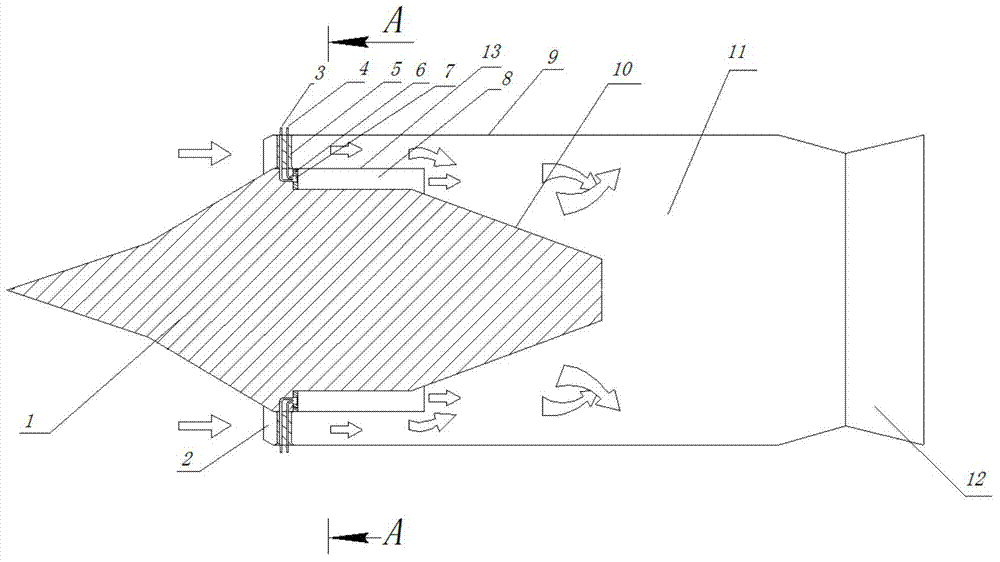
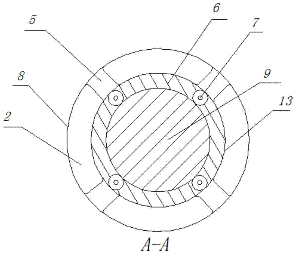
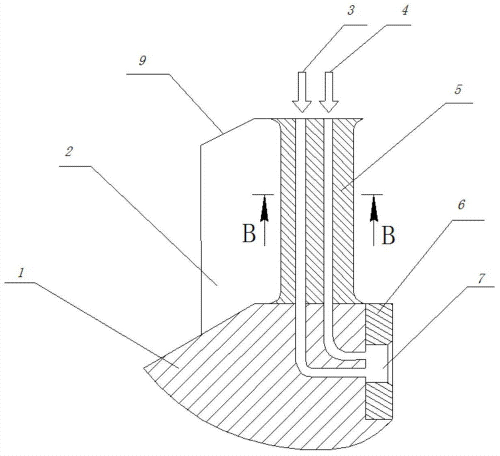
[0012] The rocket ramjet combination engine that the present invention proposes has the annular ejection structure, and its structure is as follows figure 1 As shown, it includes an engine casing 9, an inner casing 13, a rectifying head, a fixed guide column 5 and a fixed ring 6. The engine housing 9 is relatively fixed with the rectifier by the fixed guide column 5, and the fixed guide column 5 is provided with an oxidant inlet 3 and a fuel inlet 4, and the front end of the engine housing is an air inlet 2, such as figure 2 shown in . The front body 1 of rectifying head stretches out the front end of engine casing 9, and the rear body 10 of rectifying head is stepped, and step type rectifying head rear body 10 inserts in the engine casing 9, and the rear end of engine casing 9 is trumpet-shaped supersonic nozzle 12. The inner shell 13 is fixed on the middle part of the straightening head by the fixing ring 6, and the fuel oxidant mixing injection port 7 is arranged in the f...


PUM


Abstract

The invention relates to a rocket stamping combination engine with an annular injection structure, and belongs to the technical field of space equipment. An outer shell of the engine and a rectification head are oppositely fixed through a fixing guide column, an oxidizing agent inlet and a fuel inlet are formed in the fixing guide column, and an air inlet is formed in the front end of the outer shell. The front body of the rectification head stretches out of the front end of the outer shell of the engine, the rear body of the rectification head is in a step shape and is inserted into the outer shell, and a trumpet-shaped supersonic velocity nozzle is formed in the rear end of the outer shell. An inner shell is fixed in the middle of the rectification head through a fixing ring, a fuel and oxidizing agent mixing jet opening is formed in the inner shell, an annular combustion chamber is formed between the inner shell and the rectification head, and a mixed combustion chamber is formed between the outer shell and the rectification head. According to the rocket stamping combination engine, the size of the engine combustion chambers is reduced, the weight of the combination engine is reduced, and the economical performance of a power system is improved. Fuel gas is evenly sprayed out in the circumferential direction through the annular combustion chamber, the spayed fuel gas can be mixed with the air twice, and combustion efficiency is improved.

Description

technical field [0001] The invention relates to a rocket ram jet combination engine with a ring ejection structure, which belongs to the technical field of aerospace equipment. Background technique [0002] One of the key technologies of the rocket ramjet combined engine is to adopt an effective ejection rocket structure to better ensure that the engine can fully mix fuel and air as soon as possible when the engine starts at a low speed, and realize combustion in the shortest possible combustion chamber space , so that the combined engine can generate enough thrust at low speed, so as to ensure the take-off power of the combined engine at low speed. This is of great significance for realizing the structural integration of the combined engine and reducing the structural weight. In recent years, the near space, as the airspace between satellites and aircraft, has been paid more and more attention by relevant countries. The main reason is that the atmosphere in this space is ...

Claims


Application Information

Patent Timeline
Patent Type & Authority Applications(China)
IPC IPC(8): F02K7/18
Inventor 谢峤峰王兵
Owner 清航空天(浙江)科技有限公司
Learn More