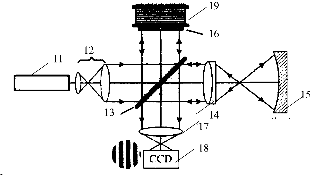
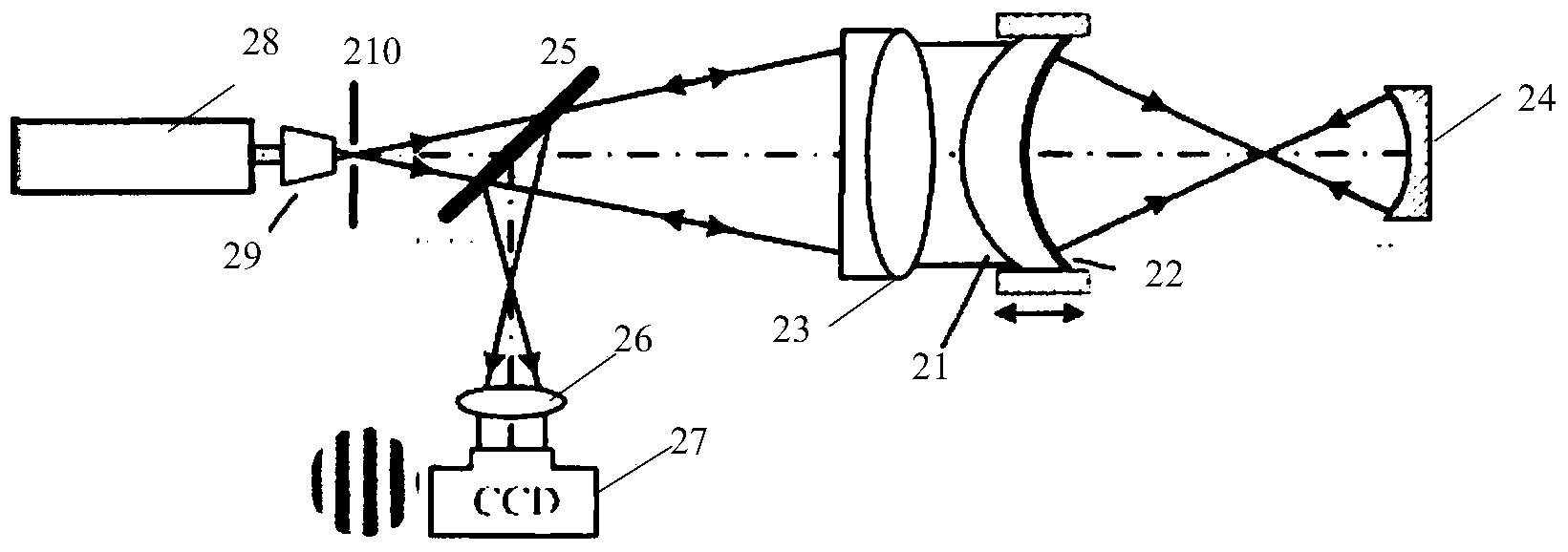
Common-path heterodyne interferometer based on phase shift of low-frequency-difference acousto-optic frequency shifter

An acousto-optic frequency shifter and a heterodyne interferometer technology, which is applied in the field of optical detection, can solve the problems of complex high-precision solution algorithms, few phase-shifting steps, and small amount of information obtained, so as to improve the anti-interference ability, Avoid moving parts and improve measurement accuracy

Active Publication Date: 2015-01-21
ACAD OF OPTO ELECTRONICS CHINESE ACAD OF SCI
View PDF7 Cites 14 Cited by
  • Summary
  • Abstract
  • Description
  • Claims
  • Application Information

AI Technical Summary

Problems solved by technology

[0008] However, due to the use of mechanical movement as a phase shifting method, the accuracy is still not high enough, the cost is high, and the development is difficult
Especially for the measurement of large-diameter surface shape, the accuracy of precision mechanical drive is reduced, and the measurement accuracy is also reduced
[0009]...

Method used


Image

  • Common-path heterodyne interferometer based on phase shift of low-frequency-difference acousto-optic frequency shifter
  • Common-path heterodyne interferometer based on phase shift of low-frequency-difference acousto-optic frequency shifter
  • Common-path heterodyne interferometer based on phase shift of low-frequency-difference acousto-optic frequency shifter

Examples


Embodiment Construction

[0026] The following describes the technical solutions in the embodiments of the present invention clearly and completely with reference to the accompanying drawings in the embodiments of the present invention. Obviously, the described embodiments are only a part of the embodiments of the present invention, not all of the embodiments. Based on the embodiments of the present invention, all other embodiments obtained by those of ordinary skill in the art without creative work shall fall within the protection scope of the present invention.

[0027] Regarding the prior art, almost all mechanical drives are used for phase shifting, which is difficult to achieve high accuracy, poor immunity, small amount of information obtained, and complicated high-precision solving algorithms.

[0028] In order to solve the above problems, the present invention adopts an acousto-optic frequency shifter to shift phase by heterodyne interference, effectively avoiding the existence of moving parts in the ...


PUM


Abstract

The invention discloses a common-path heterodyne interferometer based on the phase shift of a low-frequency-difference acousto-optic frequency shifter. The common-path heterodyne interferometer based on the phase shift of the low-frequency-difference acousto-optic frequency shifter comprises a light beam adjusting unit, a low-frequency-difference phase shifting unit, a light beam combining unit, a common-path interference unit and an area array detector unit. The light beam adjusting unit is used for adjusting output lasers of a laser device into two laser beams with identical powers. The low-frequency-difference phase shifting unit is used for adjusting the frequencies of the two laser beams obtained by the light beam adjusting unit to obtain two laser beams with the output difference frequency being a low difference frequency lower than 100 Hz. The light beam combining unit is used for carrying out beam combination on the two laser beams output by the low-frequency-difference phase shifting unit. The common-path interference unit is used for dividing the lasers combined by the light beam combining unit into common-path measuring light and reference light so as to generate interference. The area array detector unit is used for collecting the interference. According to the common-path heterodyne interferometer based on the phase shift of the low-frequency-difference acousto-optic frequency shifter, heterodyne interference phase shift of the acousto-optic frequency shifter is adopted to avoid that moving parts exist in the interferometer, the measurement accuracy is improved, the anti-interference performance is good, the anti-interference capacity is improved through the common path and the influences of the self-errors of a system light path are lowered through the common path.

Description

Technical field [0001] The invention relates to the technical field of optical detection, in particular to a common optical path heterodyne interferometer based on phase shift of a low-frequency difference acousto-optic frequency shifter. Background technique [0002] With the development of modern precision instruments, the requirements for the processing accuracy of optical surfaces are gradually increasing, and the requirements for the detection accuracy of optical surfaces are correspondingly higher. The optical surface shape detection methods used in traditional optical processing include Hartmann sensor method, knife edge method and profile method. These methods have different shortcomings, such as non-digitalization, subjective interpretation or contact damage to the DUT, and it is difficult to achieve high measurement accuracy. They are simple measurement methods. [0003] In practice, the high-precision surface shape detection is almost all done by using an interferometer...

Claims


Application Information

Patent Timeline
IPC IPC(8): G01B11/24
Inventor 张文喜李杨周志盛伍洲孔新新吕笑宇
Owner ACAD OF OPTO ELECTRONICS CHINESE ACAD OF SCI
Why Eureka
Try Eureka