
Recognition method of mine microseismic and blasting signals based on the slope of trend line of waveform onset

A signal identification and trend line technology, applied in the field of mine microseismic and blasting signal identification, can solve the problems of heavy manual identification workload, large blasting impact, and many noise sources, to avoid low identification accuracy, improve identification efficiency, and identify Efficient effect

Active Publication Date: 2017-01-18
CENT SOUTH UNIV
View PDF4 Cites 0 Cited by
  • Summary
  • Abstract
  • Description
  • Claims
  • Application Information

AI Technical Summary

Problems solved by technology

At present, when microseismic monitoring systems are used at home and abroad to monitor the stability of rock mass, they are not recognized by the site due to more or less problems. There are many and complicated, and the impact of blasting is large, resulting in a large amount of blasting data and effective microseismic information mixed together, it is difficult to accurately identify, so that it is difficult to provide intuitive monitoring data for on-site production services, and the traditional manual imprecise Waveform identification and processing can easily lead to serious errors in the rapid calibration of microseismic events and the prediction of the spatial distribution of microseismic events
Therefore, it is necessary to improve the existing signal identification methods to solve the problem of heavy and inaccurate manual identification and reduce monitoring costs

Method used


Image

  • Recognition method of mine microseismic and blasting signals based on the slope of trend line of waveform onset
  • Recognition method of mine microseismic and blasting signals based on the slope of trend line of waveform onset
  • Recognition method of mine microseismic and blasting signals based on the slope of trend line of waveform onset

Examples


Embodiment 1

[0061] The mine microseismic and blasting signal identification method based on the slope of the waveform inception trend line of the present embodiment, its steps are as follows:

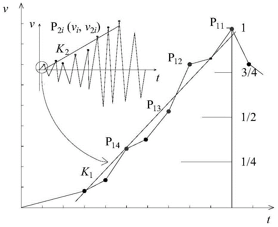
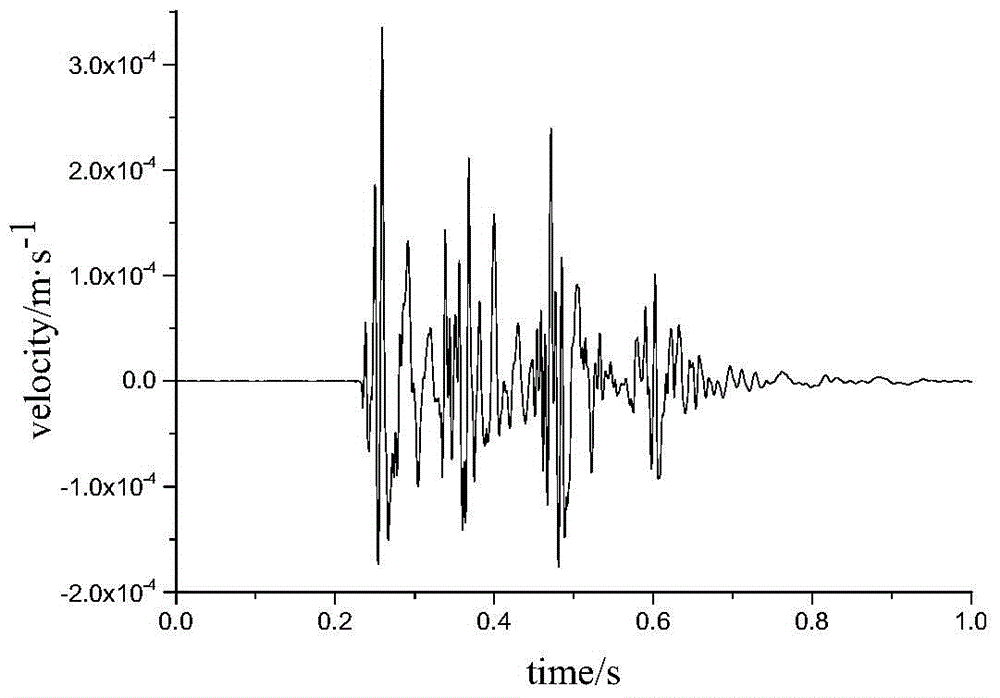
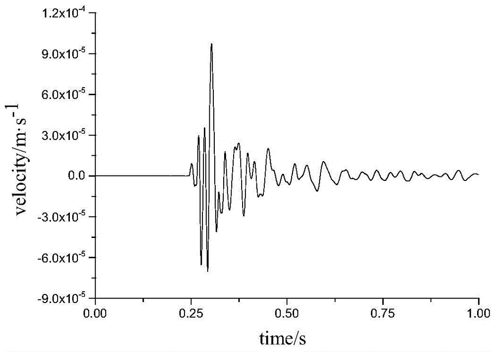
[0062] 1) Taking the first arrival point of the P wave, that is, the arrival time of the P wave recorded on the seismic waveform (the waveform record before the first arrival point of the P wave is a noise record), and the waveform segment between the first peak value of the waveform as the object, the distribution along the amplitude is sequential Select the first peak point and the 3 / 4 value closest to the first peak amplitude, and the sampling points at the 1 / 2 value and 1 / 4 value are four key data points. figure 2 The four key data points of the waveform segment before the first peak of the blasting waveform are (0.2347, 2.54E-5), (0.2340, 1.36E-5), (0.2336, 7.1E-6), (0.2305, 1.26E-7) , image 3 The four key data points of the wave segment before the first peak of the microseismic waveform ar...


PUM


Abstract

The invention discloses a mine microseism and blasting signal identification method based on a waveform oscillation starting trend line slope. The method comprises the steps that first, a linear identification equation is acquired, and a linear identification equation Y = k1 + A*k2 + B is obtained based on N groups of microseism evens and N groups of blasting events, wherein k1 and k2 are used as the parameters of the linear identification equation; second, a discrimination threshold value Yf is calculated; third, an event to be identified is identified based on the linear identification equation and the discrimination threshold value Yf, the waveform oscillation starting trend line slope of the event to be identified is calculated to obtain the k1 and the k2, the k1 and the k2 are substituted into the identification equation to obtain a Y, if the Y is smaller than or equal to the discrimination threshold value Yf, the event to be identified is a microseism event, and otherwise the event to be identified is an blasting event. According to the mine microseism and blasting signal identification method based on the waveform oscillation starting trend line slope, calculated quantity is small, identification accuracy is high, conversion from a time domain to a frequency domain is of no need, cost is low, and implementation is easy.

Description

technical field [0001] The present invention relates to a mine microseismic and blasting signal identification method, in particular to a mine microseismic and blasting signal identification method based on the slope of the waveform onset trend line. Background technique [0002] Seismic waves are mainly divided into two types, one is surface waves and the other is solid waves. Surface waves are only transmitted on the surface of the earth, and solid waves can pass through the interior of the earth. Body Wave: Transmitted inside the earth, it is divided into two types: P wave and S wave. P wave: P stands for Primary or Pressure. It is a longitudinal wave. The vibration direction of the particles is parallel to the wave's forward direction. Among all seismic waves, the forward speed is the fastest and the earliest arrives. P waves can travel in solids, liquids or gases. S wave: S means secondary (Secondary) or shear force (Shear), the forward speed is second only to P wave...

Claims


Application Information

Patent Timeline
Patent Type & Authority Patents(China)
IPC IPC(8): G01V1/28
Inventor 董陇军李夕兵马举周子龙陈光辉张楚旋
Owner CENT SOUTH UNIV
Learn More