Objective lens for endoscope and endoscope
A technology for endoscopes and endoscopes, applied in the field of endoscopes, can solve problems such as large changes, observation objects out of view, and difficult observation
- Summary
- Abstract
- Description
- Claims
- Application Information
AI Technical Summary
Problems solved by technology
Method used
Image
Examples
Embodiment 1
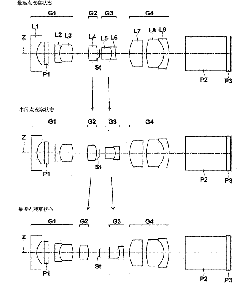
[0090] The lens configuration diagram of the objective lens for endoscope of Embodiment 1 is shown in figure 1 In , the illustration method and configuration are as described above, so repeated explanations are omitted here.
[0091] Table 1 shows basic lens data of the endoscope objective lens of Example 1. The column of Si in Table 1 indicates the i-th number (i=1, 2, 3, ...), the Ri column indicates the radius of curvature of the i-th surface, the Di column indicates the distance between the i-th surface and the i+1-th surface on the optical axis Z, and the Ndj column indicates The d-line (wavelength 587.6nm), the column of vdj indicates the Abbe number of the jth optical part to the d line.
[0092] The basic lens data also includes the aperture stop St and the optical members P1, P2, and P3, and (St) is written together with the surface number in the column of the surface number of the surface corresponding to the aperture stop St. In Table 1, the sign of the radius o...
Embodiment 2-1
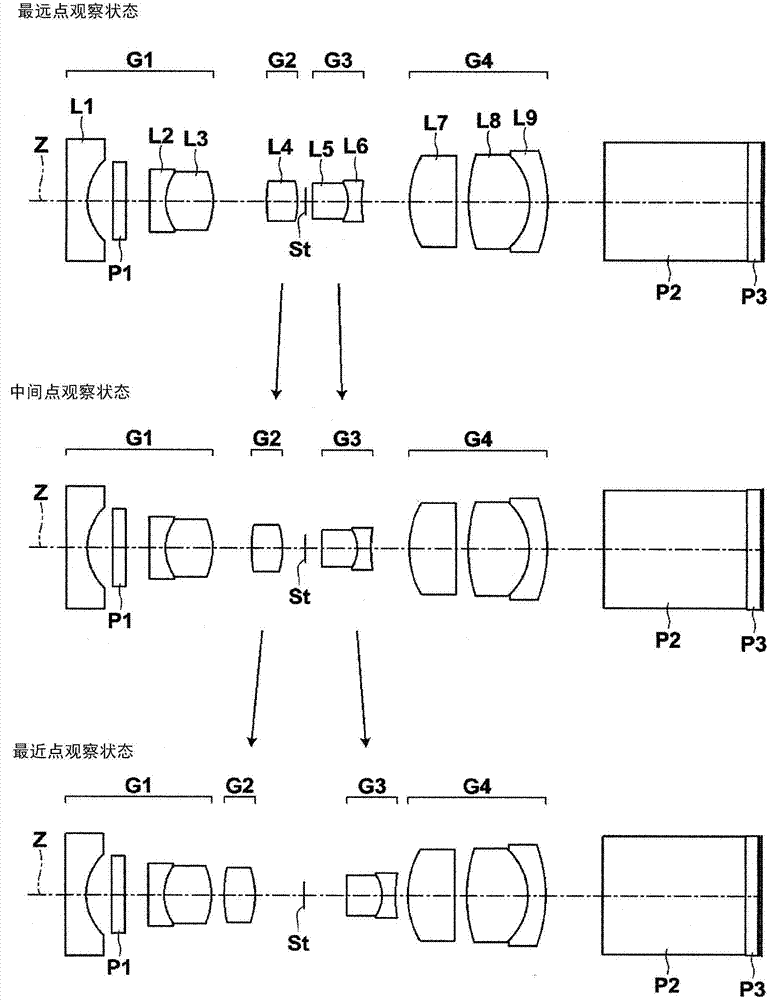
[0104] figure 2 3 shows lens configuration diagrams of the farthest point observation state, intermediate point observation state, and closest point observation state of the endoscope objective lens of Example 2-1. The basic lens data of the endoscope objective lens of Example 2-1 is the same as that of Example 1, so description of the basic lens data is omitted here. The objective lens for endoscope of Example 2-1 has the same object distance in the farthest observation state as in Example 1, but the object distances in other observation states are different from those in Example 1. Table 3 shows the farthest point observation state of the endoscope objective lens of Example 2-1, the middle and far point observation state, the middle point observation state, and the respective object distances of the closest point observation state (variable 1), (possible Change the value of 2), (variable 3), (variable 4).
[0105] 【table 3】
[0106] Example 2-1
[0107] Observa...
Embodiment 2-2
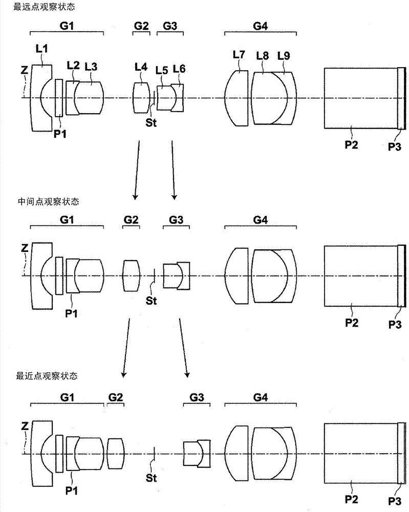
[0110] The objective lens for endoscope of embodiment 2-2, basic lens data are identical with embodiment 1, embodiment 2-1, and the object distance of farthest point observation state and the object distance of closest point observation state are the same as embodiment 2-1 of the same. Embodiment 2-1 and Embodiment 2-2 are examples in which the basic lens data, the farthest object distance, and the closest object distance are the same, but the movement trajectory is variable. Table 4 shows the farthest point observation state, middle and far point observation state, intermediate point observation state, and closest point observation state of the objective lens for endoscope of Example 2-2. Change the value of 2), (variable 3), (variable 4).
[0111] 【Table 4】
[0112] Example 2-2
[0113] Observation status
[0114] The aberration diagrams of the spherical aberration, astigmatism, distortion, and lateral chromatic aberration of the farthest point observation state...
PUM
 Abstract
Description
Claims
Application Information
 - R&D
- Intellectual Property
- Life Sciences
- Materials
- Tech Scout
- Unparalleled Data Quality
- Higher Quality Content
- 60% Fewer Hallucinations
Browse by: Latest US Patents, China's latest patents, Technical Efficacy Thesaurus, Application Domain, Technology Topic, Popular Technical Reports.
© 2025 PatSnap. All rights reserved.Legal|Privacy policy|Modern Slavery Act Transparency Statement|Sitemap|About US| Contact US: help@patsnap.com


