
Display panel mother board, display panel, manufacturing method of display panel and display device

A technology of display panel and manufacturing method, which is applied in the directions of instruments, nonlinear optics, optics, etc., can solve the problems of low transmittance and defective products, etc.

Active Publication Date: 2015-01-21
BOE TECH GRP CO LTD +1
View PDF9 Cites 5 Cited by
  • Summary
  • Abstract
  • Description
  • Claims
  • Application Information

AI Technical Summary

Problems solved by technology

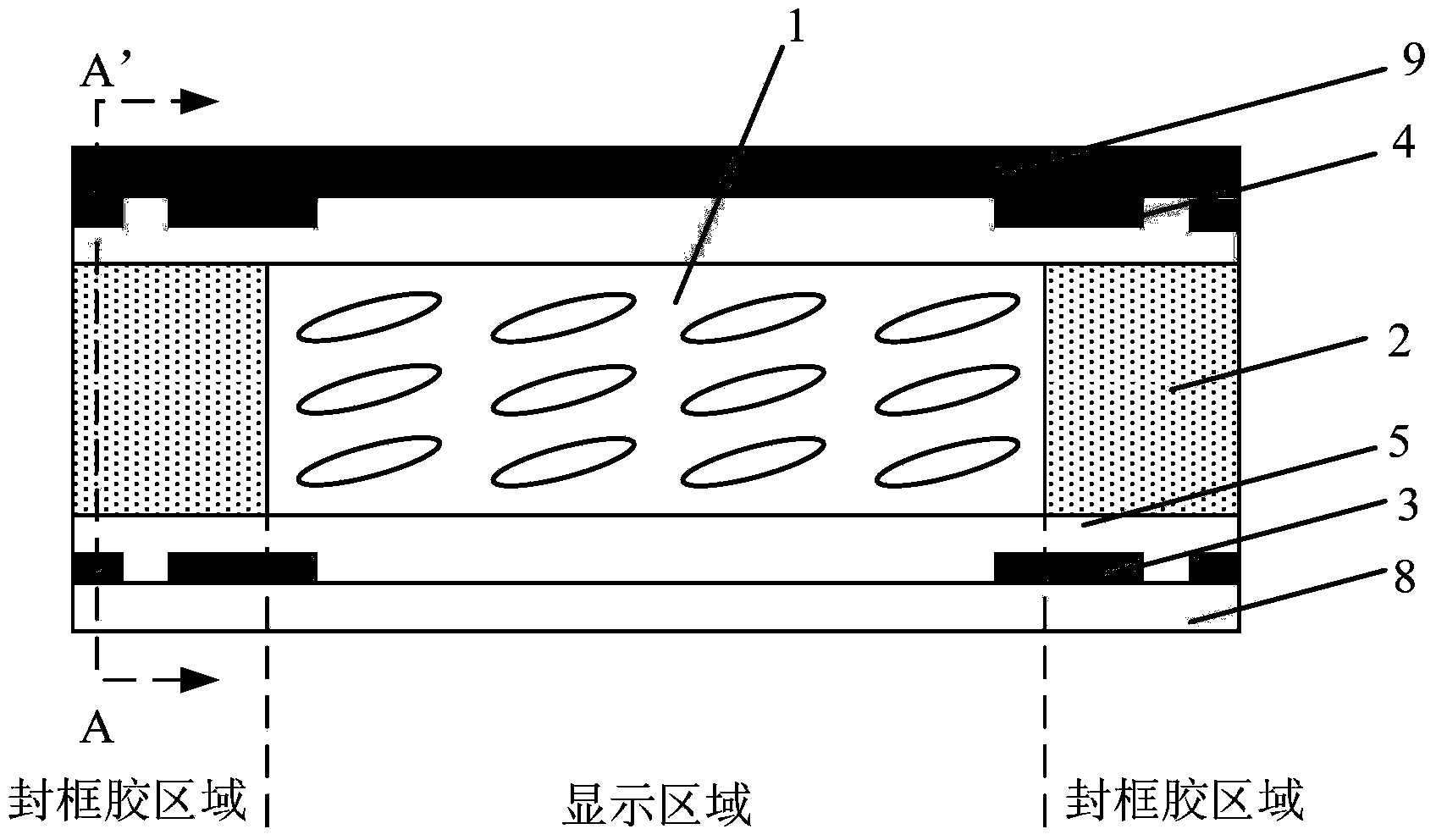
[0005] The technical problem to be solved by the present invention is how to set up the structure of the sealing glue area of ​​the display panel in the glue cutting, so that it is easy to identify the alignment scale therein for accurate alignment calibration, so as to accurately cut the motherboard of the display panel, and Helps to analyze product defects caused by alignment such as low transmittance and color mixing

Method used


Image

  • Display panel mother board, display panel, manufacturing method of display panel and display device
  • Display panel mother board, display panel, manufacturing method of display panel and display device
  • Display panel mother board, display panel, manufacturing method of display panel and display device

Examples


Embodiment Construction

[0029] In order to understand the above-mentioned purpose, features and advantages of the present invention more clearly, the present invention will be further described in detail below in conjunction with the accompanying drawings and specific embodiments. It should be noted that, in the case of no conflict, the embodiments of the present application and the features in the embodiments can be combined with each other.

[0030] In the following description, many specific details are set forth in order to fully understand the present invention. However, the present invention can also be implemented in other ways different from those described here. Therefore, the protection scope of the present invention is not limited by the specific details disclosed below. EXAMPLE LIMITATIONS.

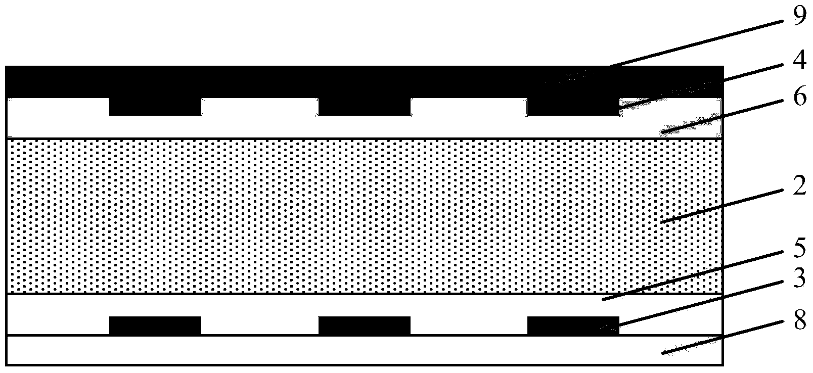
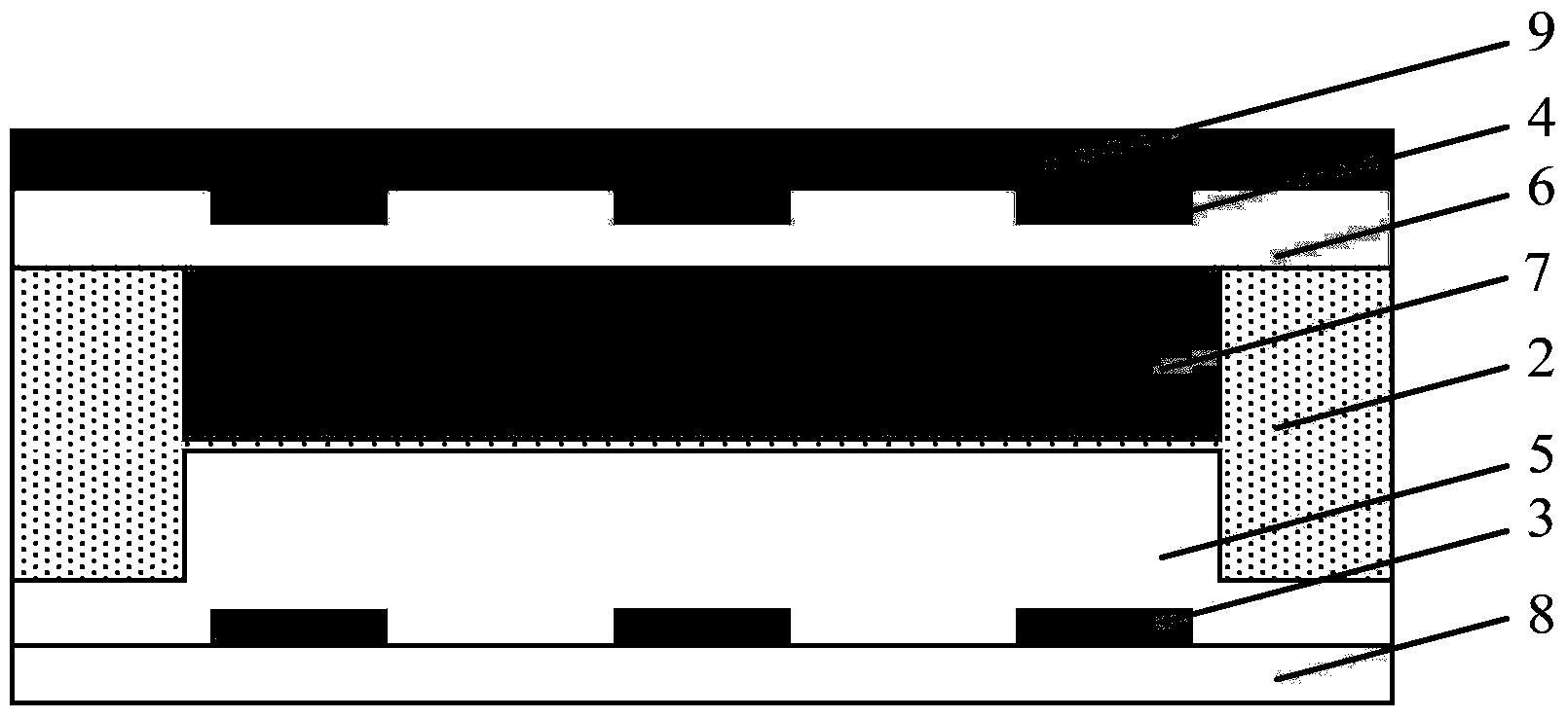
[0031] The present invention proposes a display panel motherboard, including an array substrate and a color filter substrate, wherein the array substrate includes a metal lead layer 3 and a protectiv...


PUM


Abstract

The invention relates to a display panel mother board, a manufacturing method of the display panel mother board, a display panel and a display device. The display panel mother board comprises an array substrate and a color film substrate, wherein the array substrate comprises metal lead wire layers and a protective layer, and the color film substrate comprises black matrix layers. Alignment rulers are arranged at the portions located in corresponding frame sealing adhesive areas, of each of the metal lead wire layers and the black matrix layers. Protrusions are formed at the portions corresponding to the alignment rulers in the metal lead wire layers, of the protective layer, and / or the color film substrate further comprises a spacer layer, and protrusions are formed at the portions corresponding to the alignment rulers in the black matrix layers, of the spacer layers. According to the technical scheme, the protective layer and the spacer layer are provided with the protrusions in the thickness direction of the alignment rulers in the frame sealing adhesive areas, a frame sealing adhesive is extruded during box alignment, the frame sealing adhesive between the protective layer and the spacer layer in the thickness direction of the alignment rulers is decreased, the shading degrees of the alignment rulers in the black matrix layers and the alignment rulers in the metal lead wire layers are lower, and alignment calibration conducted on the alignment rulers in the black matrix layers and the alignment rulers in the metal lead wire layers is facilitated.

Description

technical field [0001] The present invention relates to the field of display technology, in particular, to a display panel motherboard, a display device, a display panel and a manufacturing method thereof. Background technique [0002] Thin Film Transistor Liquid Crystal Display (TFT-LCD for short) occupies a dominant position in the current display field. Its products have the advantages of small size, low power consumption, no radiation, and high resolution. They have been widely used in In modern digital information equipment. With the rapid development of flat panel display technology, narrow bezel products are increasingly favored by consumers. [0003] The cutting technology with glue is an effective technical means to realize the narrow frame design of the LCD panel and increase the display area, and it has been applied by major panel manufacturers. In the adhesive cutting technology, a single frame glue is used between two adjacent panel units to separate the displ...

Claims


Application Information

Patent Timeline
IPC IPC(8): G02F1/1333G02F1/1339
CPCG02F1/133351G02F1/133512G02F1/13394G02F1/133345G02F1/1339G02F1/133354G02F1/133514G02F1/1341G02F1/13415
Inventor 姜妮李坤向西冯远明
Owner BOE TECH GRP CO LTD
Learn More