Logic chip and board card device with same
A logic chip and register technology, applied in the field of communication, can solve problems such as processor abnormal reset, debugging process interruption, low efficiency, etc., and achieve the effects of easy problem location, easy implementation, and simple design
- Summary
- Abstract
- Description
- Claims
- Application Information
AI Technical Summary
Problems solved by technology
Method used
Image
Examples
Embodiment 1
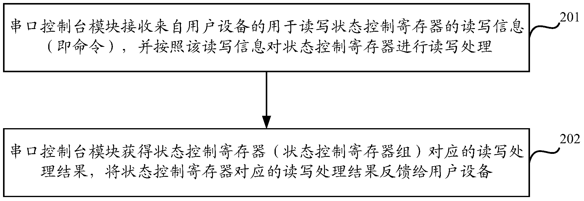
[0037] Aiming at the problems existing in the prior art, Embodiment 1 of the present invention provides a reading and writing processing method based on a serial port console module, the method is used to debug the logic chip, and the method is applied to a single board containing the logic chip . Further, the method is applied in a system including user equipment and a board device, and the board device may be a part of circuits in a complex digital circuit board.
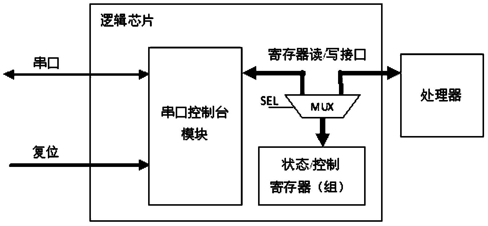
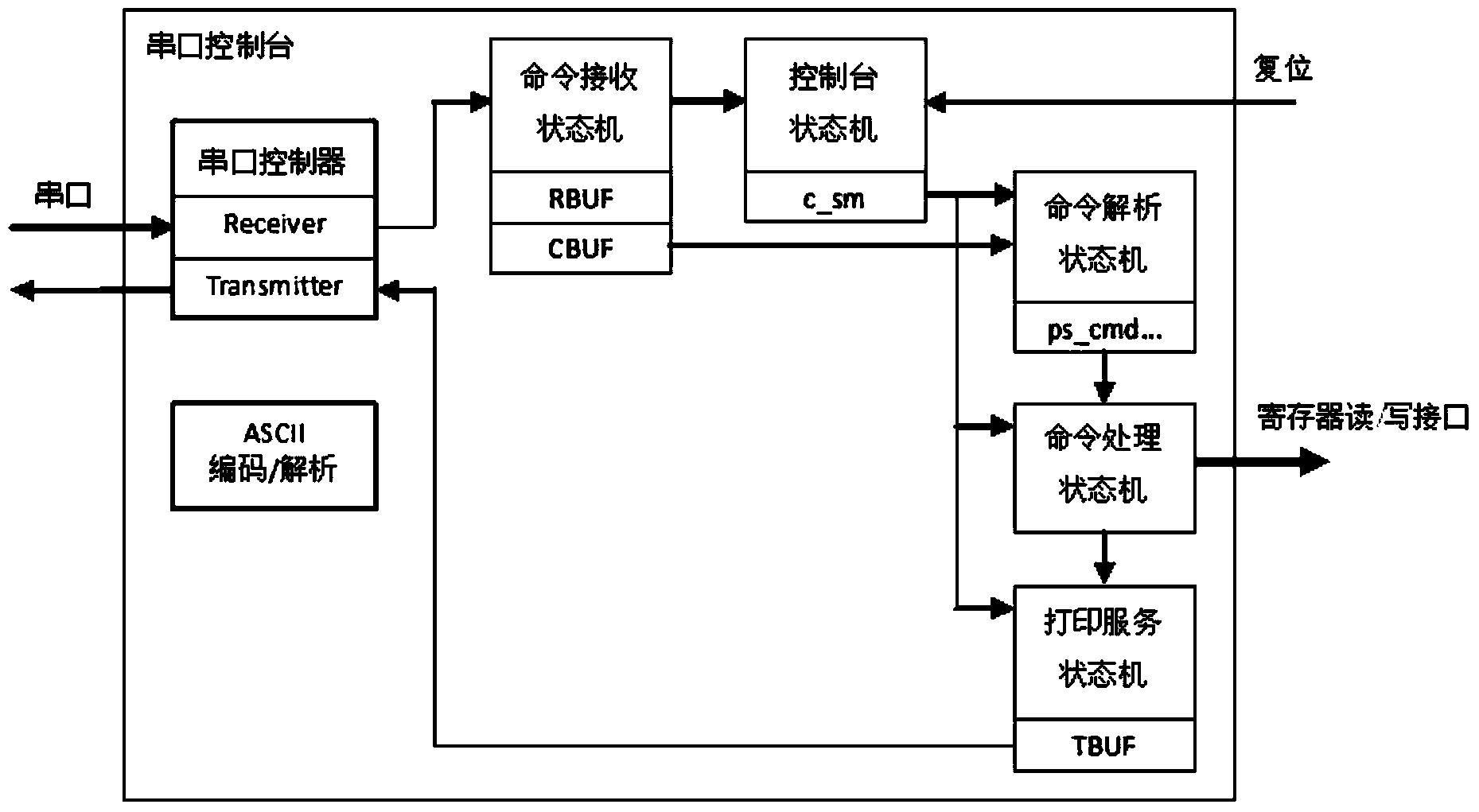
[0038] by figure 1 It is a schematic diagram of an application scenario of an embodiment of the present invention. The board device includes a logic chip and a processor. The logic chip includes a serial port console module, a MUX (multiplexer, multiplexer) and a state control register (group). Wherein, the serial port console module is connected to the user equipment through the serial port, and the user equipment provides a reset signal for the serial port console module. The MUX is connected with the serial p...
Embodiment 2
[0071] Based on the same inventive concept as the above method, a logic chip 1 is also provided in the embodiment of the present invention, such as Figure 9A As shown, the logic chip 1 specifically includes a serial console module 11, a multiplexer MUX12 and a state control register 13, the MUX12 is connected to the serial console module 11, and the MUX12 is connected to the state control register 13 connections; where,
[0072] The serial port console module 11 is configured to receive read and write information for reading and writing the state control register 13 from the user equipment, and perform read and write processing on the state control register 13 according to the read and write information; and Obtaining the reading and writing processing result corresponding to the state control register 13, and feeding back the reading and writing processing result corresponding to the state control register 13 to the user equipment.
[0073] The MUX12 is configured to determ...
Embodiment 3
[0084] Based on the same inventive concept as the above method, an embodiment of the present invention also provides a board device, the board device specifically includes the logic chip and the processor in the second embodiment above; wherein, the processor uses the register The read-write interface is connected with the MUX in the logic chip. Based on this, the MUX12 is used to determine that the mode of operation is a debug mode when receiving the decision signal; disconnect the MUX12 from the processor, and keep the MUX12 from the serial console module 11, so that the serial console module 11 is connected to the state control register 13 through the MUX12, and the state control register 13 is read and written by the serial console module 11; and , when the decision signal is not received, determine that the mode of operation is an undebug mode; disconnect the connection between the MUX12 and the serial console module 11, and keep the connection between the MUX12 and the p...
PUM
 Abstract
Description
Claims
Application Information
 - R&D
- Intellectual Property
- Life Sciences
- Materials
- Tech Scout
- Unparalleled Data Quality
- Higher Quality Content
- 60% Fewer Hallucinations
Browse by: Latest US Patents, China's latest patents, Technical Efficacy Thesaurus, Application Domain, Technology Topic, Popular Technical Reports.
© 2025 PatSnap. All rights reserved.Legal|Privacy policy|Modern Slavery Act Transparency Statement|Sitemap|About US| Contact US: help@patsnap.com


