Method and system for calibrating camera for lane offset early warning

A technology of lane deviation and calibration method, which is applied in the field of lane deviation warning, can solve the problems of high time cost, low accuracy, high time cost and system cost, and achieves improved accuracy and work efficiency, simplified site and steps, shortened The effect of calibration time

Active Publication Date: 2015-01-21
SHANGHAI RAPTOR AUTOMOTIVE CO LTD
View PDF5 Cites 34 Cited by
  • Summary
  • Abstract
  • Description
  • Claims
  • Application Information

AI Technical Summary

Problems solved by technology

[0007] (1) This calibration method requires manual measurement of many parameters, including the installation height of the camera, the horizontal installation position of the camera, the distance between the camera and the wheel, and the distance between the camera and the front of the car. There are errors in the manual measurement of each parameter. The accumulated error of the parameters is even greater, so the accuracy is not high and the time cost is high;
[0008] (2) The manual operation of this calibration method is complicated, and a calibration board needs to be placed 2 meters in front of the vehicle, and the cursor on the LCD display interface is moved and displayed through the human-computer interaction unit, so that the center point of the camera is moved to the reference center of the calibration board Point contour position, so as to calculate the pitch angle, rotation angle an...

Method used


Image

  • Method and system for calibrating camera for lane offset early warning
  • Method and system for calibrating camera for lane offset early warning
  • Method and system for calibrating camera for lane offset early warning

Examples


Embodiment Construction

[0053] In order to make the object, technical solution and advantages of the present invention clearer, the present invention will be further described in detail below in conjunction with the accompanying drawings and embodiments. It should be understood that the specific embodiments described here are only used to explain the present invention, not to limit the present invention.

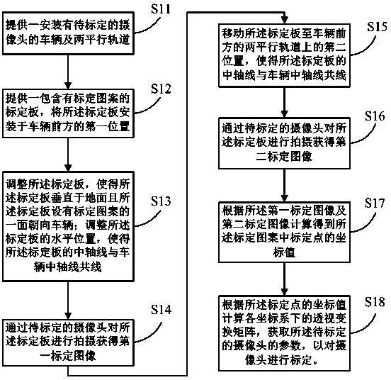
[0054] The invention provides a camera calibration method for lane departure warning, comprising the following steps:

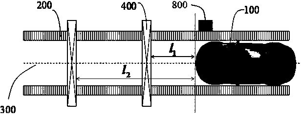
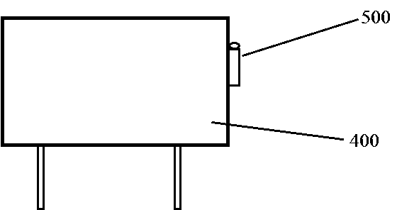
[0055] placing the calibration plate containing the calibration pattern at a first position in front of the vehicle so that the central axis of the calibration plate is collinear with the central axis of the vehicle, and the calibration plate is photographed by the camera to be calibrated to obtain a first calibration image; Moving the calibration plate to a second position in front of the vehicle so that the central axis of the calibration plate is collinear with the central axis...


PUM


Abstract

The invention discloses a method and system for calibrating a camera for lane offset early warning. The method comprises the following steps that a calibration plate including calibration patterns is arranged at a first position in front of a vehicle, the central axis of the calibration plate and the central axis of the vehicle are made to be collinear, and the calibration plate is shot through a camera to be calibrated to obtain a first calibration image; the calibration plate is moved to a second position in front of the vehicle, the central axis of the calibration plate and the central axis of the vehicle are made to be collinear, and the calibration plate is shot through the camera to be calibrated to obtain a second calibration image; the coordinate values of a calibration point in the calibration patterns are obtained through calculation according to the first calibration image and the second calibration image, and the camera to be calibrated is calibrated according to the coordinate values of the calibration point. By means of the method and system for calibrating the camera for lane offset early warning, the operand of image processing and manual measurement parameters in an early stage are reduced, the site and the steps for calibration are simplified, the calibration time is shortened, so that the calibration precision and the calibration working efficiency of the camera are improved, and the method and system are suitable for large scale flow line production operation in large vehicle factories.

Description

technical field [0001] The invention relates to the technical field of lane departure warning, in particular to a camera calibration method and system for lane departure warning. Background technique [0002] Lane Departure Warning System (Lane Departure Warning System, LDW) is a camera that captures the road conditions in front of the vehicle, detects the relationship between the lane markings on the road surface and the vehicle's driving vector to determine whether the vehicle has drifted, and then An active safety driving system that reminds the driver to correct the driving direction when there is a deviation. The system parameters of the camera and the lane departure warning system need to be calibrated before the system is used. By establishing the relationship between the two-dimensional ground world coordinate system and the two-dimensional screen coordinate system, it is mainly to solve the perspective transformation matrix of the two coordinate systems, so as to de...

Claims


Application Information

Patent Timeline
IPC IPC(8): G06T7/00
CPCG06T7/80G06T2207/10016
Inventor 杜孙正彭卓韬段拥政
Owner SHANGHAI RAPTOR AUTOMOTIVE CO LTD
Why Eureka
Try Eureka