Power distribution cabinet

A combination of power distribution cabinet and isolation board technology, applied in substation/distribution device housing, belt/chain/gear, mechanical equipment, etc., to achieve the effect of expanding the installable area, easy operation, and ensuring coordination

Active Publication Date: 2015-01-21
湘乡市华龙电力器材有限公司
View PDF5 Cites 4 Cited by
  • Summary
  • Abstract
  • Description
  • Claims
  • Application Information

AI Technical Summary

Problems solved by technology

[0004] Aiming at the deficiencies of the prior art, the purpose of the present invention is to provide a power distribution cabinet to solve the problems of reducing the floor area of ​​the power distribution cabinet, making full use of the space of the power distribution cabinet and improving the rainproof effect of the power distribution cabinet

Method used


Image

  • Power distribution cabinet
  • Power distribution cabinet
  • Power distribution cabinet

Examples


Embodiment Construction

[0019] Preferred embodiments of the present invention will be described in detail below in conjunction with the accompanying drawings.

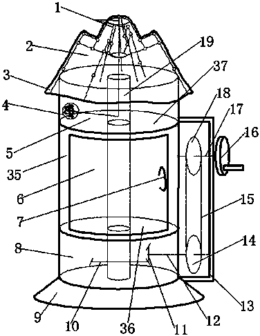
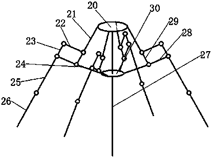
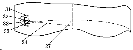
[0020] Such as figure 1 , figure 2 as well as image 3 As shown, a power distribution cabinet includes a circular shell 35 and a base 9, the circular shell 35 is provided with a base 9, and the top of the circular shell 35 is provided with a rainproof device, and the rainproof device includes a rain cloth 3 and a bracket 2, and the bracket 2. The outer side is connected to the rain cloth 3. The support frame 2 includes a fixed dome plate 20, a movable dome plate 30 is set under the fixed dome plate 20, and a main shaft 27 is arranged in the middle of the fixed dome plate 20 and the movable dome plate 30. The main shaft 27 and the movable dome plate Be non-detachable connection between the top plate 30 and the fixed dome plate 20, one end of the connecting rod 1 is connected to the fixed dome plate 20, and the other end is connected to the ...


PUM


Abstract

The invention discloses a power distribution cabinet which comprises a circular shell and a base. The circular shell is arranged on the base. A rainproof device is arranged on the top of the circular shell. A cylindrical rod is arranged in the circular shell. A first partition plate is arranged at the upper portion of the interior of the circular shell. A second partition plate is arranged at the lower portion of the interior of the circular shell. A first cavity is formed in the region between the first partition plate and the top of the circular shell. A second cavity is formed in the region between the second partition plate and the bottom of the circular shell. A rainproof starting locking device is arranged at the position, corresponding to the first cavity, of the exterior of the circular shell. A glass door is arranged at the position, between the first partition plate and the second partition plate, of the outer side of the circular shell. A handle is arranged on the glass door. A rocking box is arranged on one side of the glass door. A rocking mechanism is arranged in the rocking box and the second cavity. A handle stem is arranged on the outer side of the rocking box. An electrical component is arranged on the side face of the cylindrical rod. According to the power distribution cabinet, the purposes that the floor space of the power distribution cabinet is decreased, the space of the power distribution cabinet is sufficiently utilized and the rainproof effect of the power distribution cabinet is improved are achieved.

Description

technical field [0001] The invention relates to the technical field of power distribution equipment, in particular to a power distribution cabinet. Background technique [0002] The power distribution cabinet is the final equipment of the power distribution system, and it is the general name of the motor control center. The power distribution cabinet is used in the occasions where the load is relatively scattered and there are few circuits; the motor control center is used in the occasions where the load is concentrated and there are many circuits. They distribute the electric energy of a certain circuit of the upper-level power distribution equipment to the nearest load. [0003] The current power distribution cabinets are generally heavy and occupy a large area. The general power distribution cabinets are not effective in preventing rain. There are not many electronic parameters that can be viewed in the general power distribution cabinets. From the perspective of saving ...

Claims


Application Information

Patent Timeline
Patent Type & Authority Applications(China)
IPC IPC(8): H02B1/28F16H37/02
CPCH02B1/28
Inventor 钱玉明
Owner 湘乡市华龙电力器材有限公司
Why Eureka
Try Eureka