Multifrequency microwave rectifier circuit

A rectifier circuit and microwave technology, applied in electrical components, irreversible AC power input to DC power output, output power conversion devices, etc., can solve the problems of diode impedance matching, difficult harmonic suppression, and signal input without filtering In order to achieve the effect of ultra-wideband rectification, harmonic suppression and multi-frequency rectification

Inactive Publication Date: 2015-01-21
ZHEJIANG TEXTILE & FASHION COLLEGE
View PDF6 Cites 1 Cited by
  • Summary
  • Abstract
  • Description
  • Claims
  • Application Information

AI Technical Summary

Problems solved by technology

There are many studies on single-channel multi-frequency impedance matching in power amplifiers. If it is applied to environmental microwave energy rectification, it will be difficult to achieve multi-frequency rectification in the short term.
[0004] The current multi-frequency and ultra-wideband rectifier circuit directly connects the diode to the ultra-wideband antenna, allowing it to directly convert the signal, which has the following disadvantages: 1) There is no filter at the signal input end, which makes it difficult to suppress harmonics and reduce the diode Rectification efficiency; 2) Without an impedance transformation circuit, it is impossible to perform impedance matching on the diode, and it is impossible to achieve high-efficiency rectification

Method used


Image

  • Multifrequency microwave rectifier circuit

Examples


Embodiment Construction

[0009] The present invention will be further described in detail below in conjunction with the accompanying drawings and embodiments.

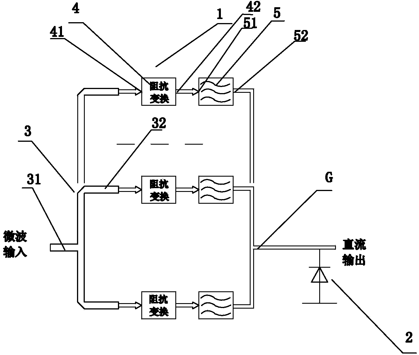
[0010] A multi-frequency microwave rectification circuit, including an input matching network 1 and a rectifying diode 2, the input matching network 1 includes a power divider 3, an impedance converter group composed of a plurality of impedance converters 4 and a filtering filter composed of a plurality of filters 5 The power divider 3 includes an input terminal 31 for microwave input and at least two output terminals 32, and each output terminal 32 of the power divider 3 is connected to the input terminal 41 of each impedance converter 4, and each impedance The output terminal 42 of the converter 4 is connected to the input terminal 51 of each filter 5, and the output terminals 52 of all the filters 5 form a common terminal G for direct current output, and the cathode of the rectifier diode 2 is connected to the common terminal G, rectify...


PUM


Abstract

The invention discloses a multifrequency microwave rectifier circuit. The multifrequency microwave rectifier circuit comprises an input matching network and a rectifier diode. The input matching network comprises a power divider, an impedance transformer bank composed of a plurality of impedance transformers and a filter bank composed of a plurality of filters. The power divider comprises an input end for input of microwaves and at least two output ends, wherein each output end of the power divider is connected with the input end of the corresponding impedance transformer, the output end of each impedance transformer is connected with the input end of the corresponding filter, the output ends of all the filters form a common end for output of direct current, the negative electrode of the rectifier diode is connected with the common end, and the positive electrode of the rectifier diode is grounded. The multifrequency microwave rectifier circuit has the advantages that multifrequency rectification can be achieved, and ultra-wideband rectification can also be achieved; impedance of multiple specific frequency bands of the diode can be transformed; harmonic suppression can be achieved, and the rectification efficiency of the diode can be improved.

Description

technical field [0001] The invention relates to a rectifier circuit applied to microwave energy transmission and environmental microwave energy reception, in particular to a multi-frequency microwave rectifier circuit. Background technique [0002] Battery life is a problem for all kinds of smart terminals, and it is also a problem for wireless sensors to work continuously. At present, both at home and abroad are studying how to convert excess energy in the environment, such as light energy, temperature difference and vibration, into electrical energy for continuous operation of low-power electronic devices by capturing excess energy in the environment. The energy captured from the environment is continuous and free. As the energy consumption of components continues to decrease, the application prospects of these energy are unanimously optimistic. In fact, there is an invisible energy around us—microwaves. Microwave energy has been widely and deeply researched at home and a...

Claims


Application Information

Patent Timeline
Patent Type & Authority Applications(China)
IPC IPC(8): H02M7/06H02M1/14
CPCH02M1/12H02M7/06H02M1/0083
Inventor 张海力陈罡张羽
Owner ZHEJIANG TEXTILE & FASHION COLLEGE
Why Eureka
Try Eureka