Friction generator

A triboelectric generator and electrode layer technology, applied in the direction of triboelectric generators, etc., can solve the problems of restricting the development and application of generator output power, and achieve the effects of large output power, high output power and simple preparation process.

Active Publication Date: 2015-01-21
NEWNAGY TANGSHAN
View PDF7 Cites 26 Cited by
  • Summary
  • Abstract
  • Description
  • Claims
  • Application Information

AI Technical Summary

Problems solved by technology

At present, nanogenerators have been able to drive small liquid crystal displays, low-power light-emitting diodes, and microelectr

Method used


Image

  • Friction generator
  • Friction generator
  • Friction generator

Examples


Embodiment 1

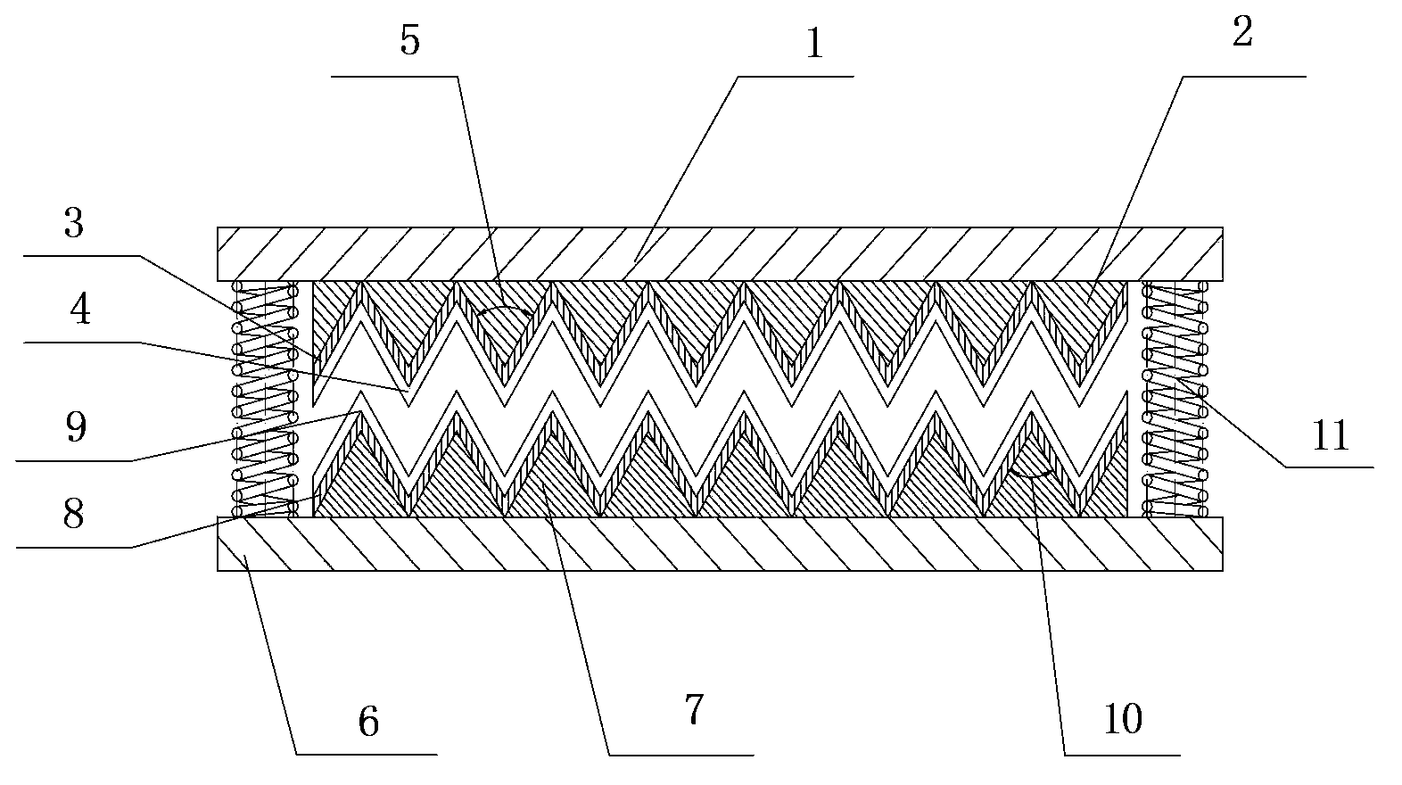
[0064] Such as figure 1 Triboelectric generator

[0065] (1) Take two square acrylic plates as the first substrate and the second substrate, the size of which is 10cm*10cm*1cm, and drill four holes in the four corners of the two square substrates for installing springs.

[0066] (2) Bonding the sponge to the first substrate prepared in step (1), the shape of the sponge protrusion is a regular pyramid (that is, the dihedral angle between the bottom surface of the regular pyramid and the sides of the regular pyramid is 60 degrees) , the size of the bottom surface of the regular square pyramid is 2mm*2cm, and the regular square pyramids are arranged in sequence with common sides; the acrylic is bonded to the second substrate prepared in step (1), and the shape of the acrylic depression is a regular square pyramid, and the regular square pyramid The dihedral angle between the bottom surface and the sides of the quadrangular pyramid is 62 degrees, and the side length of the bottom...

Embodiment 2

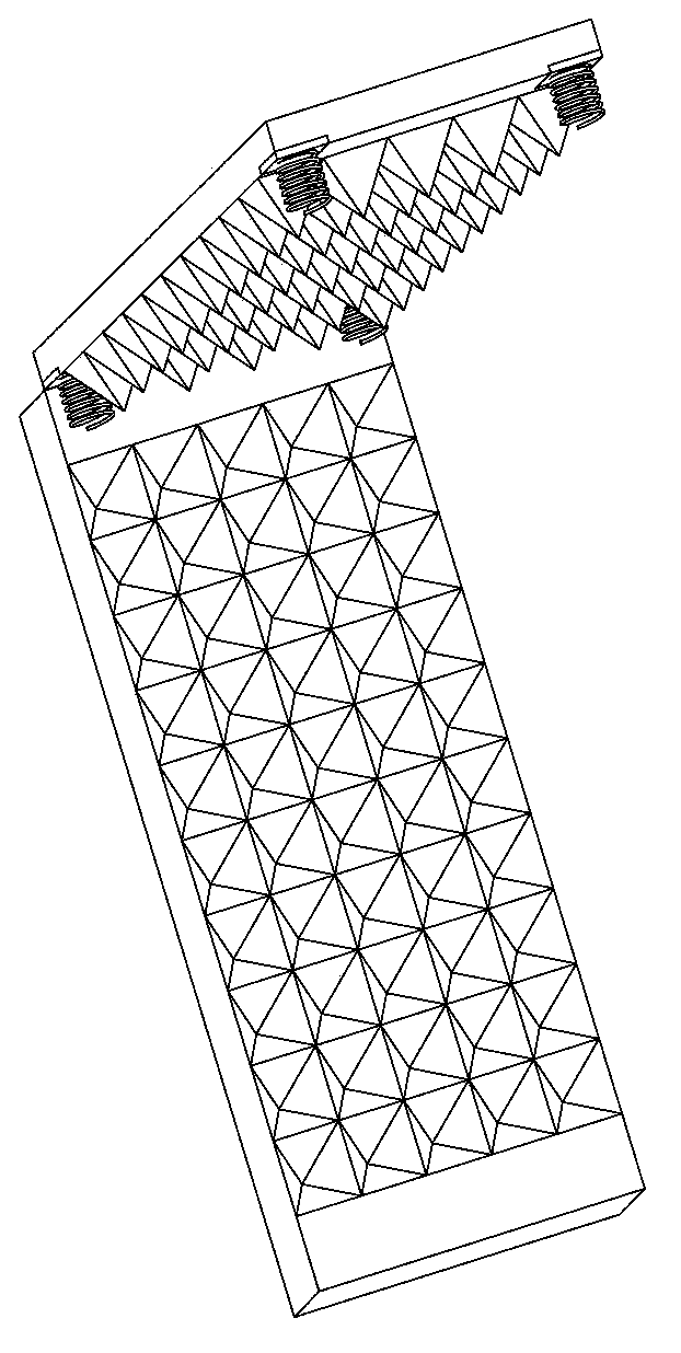
[0070] Such as Figure 3a with Figure 3b The friction generator is prepared as shown, wherein, Figure 3a is the three-dimensional view of the prepared triboelectric generator, Figure 3b Plan view of the prepared triboelectric generator.

[0071] (1) Take two square acrylic plates as the first substrate and the second substrate, the size of which is 10cm*10cm*1cm, and drill four holes in the four corners of the two square substrates for installing springs.

[0072] (2) Bonding the sponge to the first substrate prepared in step (1), the shape of the sponge protrusion is a regular triangular prism, wherein the dihedral angle between the surface of the first substrate and the side of the regular triangular prism is 120 degrees , the base length of the regular triangular prism cross-section triangle is 2 mm, and the regular triangular prisms are arranged in sequence with common sides; the acrylic is bonded to the second substrate prepared in step (1), and the shape of the acr...

Embodiment 3

[0076] Such as Figure 4a with Figure 4b The friction generator is prepared as shown, wherein, Figure 4a is the three-dimensional view of the prepared triboelectric generator, Figure 4b Plan view of the prepared triboelectric generator.

[0077] (1) Take two square acrylic plates as the first substrate and the second substrate, the size of which is 10cm*10cm*1cm, and drill four holes in the four corners of the two square substrates for installing springs.

[0078] (2) Bond the sponge to the first substrate prepared in step (1). The shape of the sponge protrusion is a cuboid (the length, width and height of the cuboid are 3mm*3mm*6mm), distributed in an array, and two adjacent cuboids The distance between them is square, and its size is 2.5mm*2.5mm; the acrylic is bonded to the second substrate prepared in step (1), and the shape of the acrylic protrusion is also a cuboid (the length, width and height of the cuboid are 2.5mm *2.5mm*6mm), array distribution, the interval ...


PUM


Abstract

The invention provides a friction generator which includes a first base plate, a second base plate and multiple elastic components. The first base plate is arranged opposite to the second base plate; and the first base plate and the second base plate are connected to each other through the multiple elastic components in a supported manner. A first support material layer, a first electrode layer and a first macromolecular polymer insulation layer are orderly disposed, in the direction opposite to the second base plate, on the first base plate; and a second support material layer, a second electrode layer and a second macromolecular polymer insulation layer are orderly disposed, in the direction opposite to the first base plate, on the second base plate. The cross sections, in the direction perpendicular to the base plates, of the first support material layer and the second support material layer are zigzag in shape. The invention also provides a friction generator set which is composed of at least two friction generators connected in series or in parallel.

Description

technical field [0001] The invention relates to the field of nanotechnology, in particular to the field of a nanogenerator for triboelectric power generation. Background technique [0002] Energy harvesting and conversion devices constructed using nanotechnology, which play a key role in self-powered nanosystems, have attracted increasing attention due to their environmental protection, energy-saving, and self-driving properties. Since the piezoelectric nanogenerator developed by Professor Wang Zhonglin's research group converted mechanical energy into electrical energy for the first time, nanogenerators with different structures and materials based on piezoelectricity and triboelectricity have come out one after another. At present, nanogenerators have been able to drive small liquid crystal displays, low-power light-emitting diodes, and microelectronic devices and modules, etc., but the output power of the generator is still a key factor restricting its development and app...

Claims


Application Information

Patent Timeline
IPC IPC(8): H02N1/04
Inventor 王珊冯顺王小雄郭竟
Owner NEWNAGY TANGSHAN
Why Eureka
Try Eureka