Four-wheel reclamation machine

A four-wheel drive and walking mechanism technology, applied in the field of agricultural and forestry machinery, can solve problems such as high labor intensity, increased production costs, and low efficiency of manual excavation

Active Publication Date: 2015-01-28
安徽铸星机械制造有限公司
View PDF5 Cites 9 Cited by
  • Summary
  • Abstract
  • Description
  • Claims
  • Application Information

AI Technical Summary

Problems solved by technology

[0003] At present, it is known that the holes used for transplanting trees, field ditching and burying electric poles are generally excavated by hand, which is inefficient and labor-intensive.
In particular, sawing is used for felling trees, and the large end and root wood of the tree are all buried in the soil, causing waste and greatly increasing production costs.

Method used


Image

  • Four-wheel reclamation machine
  • Four-wheel reclamation machine
  • Four-wheel reclamation machine

Examples


Embodiment 1

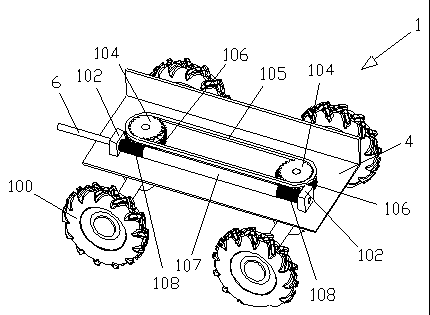
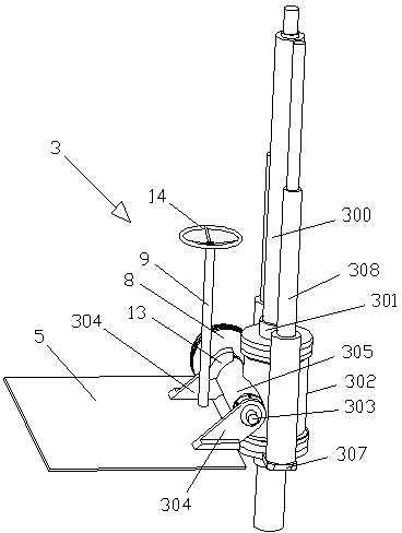
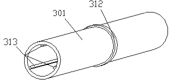
[0055] When the groove needs to be opened, the angle adjustment worm 9 is driven by the adjustment plate 14 on the angle adjustment worm 9, and the fan-shaped worm wheel 13 is driven by the angle adjustment worm 9. Meanwhile, the worm housing 305 and the main power head shell 302 are also followed to adjust the inclination angle of the end milling screw cutter 300. At this time, the diesel engine 200 is used to drive the travel sprocket 104 to rotate by the travel hydraulic motor 201, so that the wheel 100 travels, and the pulley 8 is also driven to rotate at the same time. The driving head screw 303 rotates to drive the rotating worm gear 312 on the rotating sleeve 30301. At this time, the end milling screw 300 also rotates accordingly to perform groove opening.

Embodiment 2

[0057] When the ground hole needs to be drilled, the angle adjustment worm 9 is driven by the adjustment disk 14 on the angle adjustment worm 9, and the fan-shaped worm wheel 13 is driven by the angle adjustment worm 9. Meanwhile, the worm housing 305 and the main power head housing 302 also follow and adjust the end mill screw cutter 300 to a vertical angle, start the diesel engine 200, and at the same time the pulley 8 will also be driven to rotate, so that the main power head screw 303 rotates to drive the rotating worm gear 312 on the rotating sleeve 301. At this time, the end milling screw cutter 300 also rotates accordingly. When it is necessary to give the ground hole a depth, the hydraulic lifting rod 308 is controlled to descend through the hydraulic pump station, and drives the milling screw cutter 300 to descend in the rotating sleeve 301, thereby Reach the depth required for the ground hole.

Embodiment 3

[0059] When it is necessary to dig trees and transplant seedlings, when the bottom end of the end milling helical cutter 300 is aligned near the base of the tree or seedlings, the angle adjustment worm 9 is driven by the adjustment disc 14 on the angle adjustment worm 9, and the angle adjustment worm 9 is used to adjust the angle. Drive the fan-shaped worm gear 13, and at the same time, the worm housing 305 and the main power head housing 302 also move accordingly, thereby adjusting the inclination angle of the end milling screw cutter 300, and driving the vertical direction rod 10 by rotating the direction rotating disc 12 , and then through the bevel gear b 11 at the bottom of the vertical direction rod 10, and the bevel gear a 7 is driven by the bevel gear b 11 to drive the direction linkage rod 6 to rotate. At this time, the worm 107 will also rotate thereupon, because the worm The worm gears 108 at both ends of the 107 are arranged in opposite directions, so that the worm ...


PUM


Abstract

The invention discloses a four-wheel reclamation machine, belonging to the field of machines. The four-wheel reclamation machine comprise a traveling mechanism and a power mechanism as well as a reclamation mechanism for reclamation, wherein the traveling mechanism is arranged below a base, a bottom plate is arranged above the base, the power mechanism is arranged on the base plate, and the reclamation mechanism is fixed above one side of the bottom plate. The reclamation machine can be used to dig a trench, drill a ground hole, move a tree and transplant a seedling.

Description

technical field [0001] The invention relates to an agricultural and forestry machine, in particular to a reclamation machine for trenching, drilling, tree digging and transplanting seedlings. Background technique [0002] With the continuous development of landscaping, the area occupied by nurseries has also increased. The traditional transplantation of trees in nurseries requires manually digging out the trees before they can be transplanted and cultivated. Because the trees are relatively large and the root systems are relatively large, therefore , The transplantation of trees is a huge project. [0003] At present, it is known that the holes for transplanting trees, field ditching and burying electric poles are usually manually excavated, which is inefficient and labor-intensive. Especially when felling trees, sawing is used, and the large-end root timber of the tree is all buried in the soil, which causes waste and greatly increases the production cost. Contents of th...

Claims


Application Information

Patent Timeline
Patent Type & Authority Applications(China)
IPC IPC(8): A01C5/06A01C5/04A01G23/04A01G23/06B62D3/04B62D11/02
Inventor 周晓明
Owner 安徽铸星机械制造有限公司
Why Eureka
Try Eureka