
Steel wire rope dirt-removing oiling machine

A steel wire rope and oiler technology, which is applied in the auxiliary devices, cleaning methods and utensils of rope making, and cleaning methods using tools, etc. problem, to achieve a significant effect

Active Publication Date: 2015-01-28
ZAOZHUANG FUYUAN ENVIRONMENTAL PROTECTION & ENERGY SAVING MACHINERY MFG CO LTD
View PDF8 Cites 14 Cited by
  • Summary
  • Abstract
  • Description
  • Claims
  • Application Information

AI Technical Summary

Problems solved by technology

[0002] The steel wire rope is one of the components of the lifting equipment. It is easy to corrode, wear and chemically attack to reduce the performance. It needs to be maintained regularly. During the maintenance process, dust and sand should be removed and oiled according to regulations. The traditional method is to use manual descaling and grease. Carrying out maintenance, the effect is poor, wasting manpower and material resources, and the descaling and smearing grease is uneven, there will be potential safety hazards. The inventor participated in the design of the steel wire rope suspension maintenance machine, patent number: 201320054504.2. After field tests, it is not possible to use jointless The wire rope is suspended in the air for cleaning and maintenance, because the two ends of the wire rope are connected up and down during work, and cannot be disconnected, and cannot be put into the wire rope suspension maintenance machine. To remove the dry and old sludge in the spiral groove of the steel wire rope, the brush roller can only remove the surrounding surface of the steel wire rope, but it consumes too much oil and causes waste. In addition, due to the small distance between the suspended steel wire rope and the steel wire rope Inoperable, the design of the original invention does not meet the wire rope maintenance standards in the above environment

Method used


Image

  • Steel wire rope dirt-removing oiling machine
  • Steel wire rope dirt-removing oiling machine
  • Steel wire rope dirt-removing oiling machine

Examples


Embodiment Construction

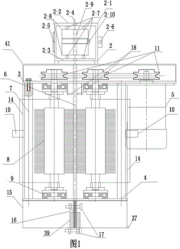
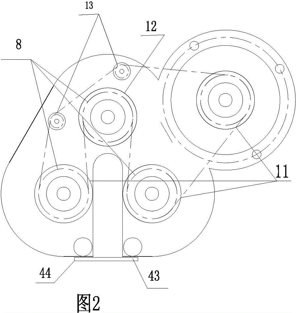
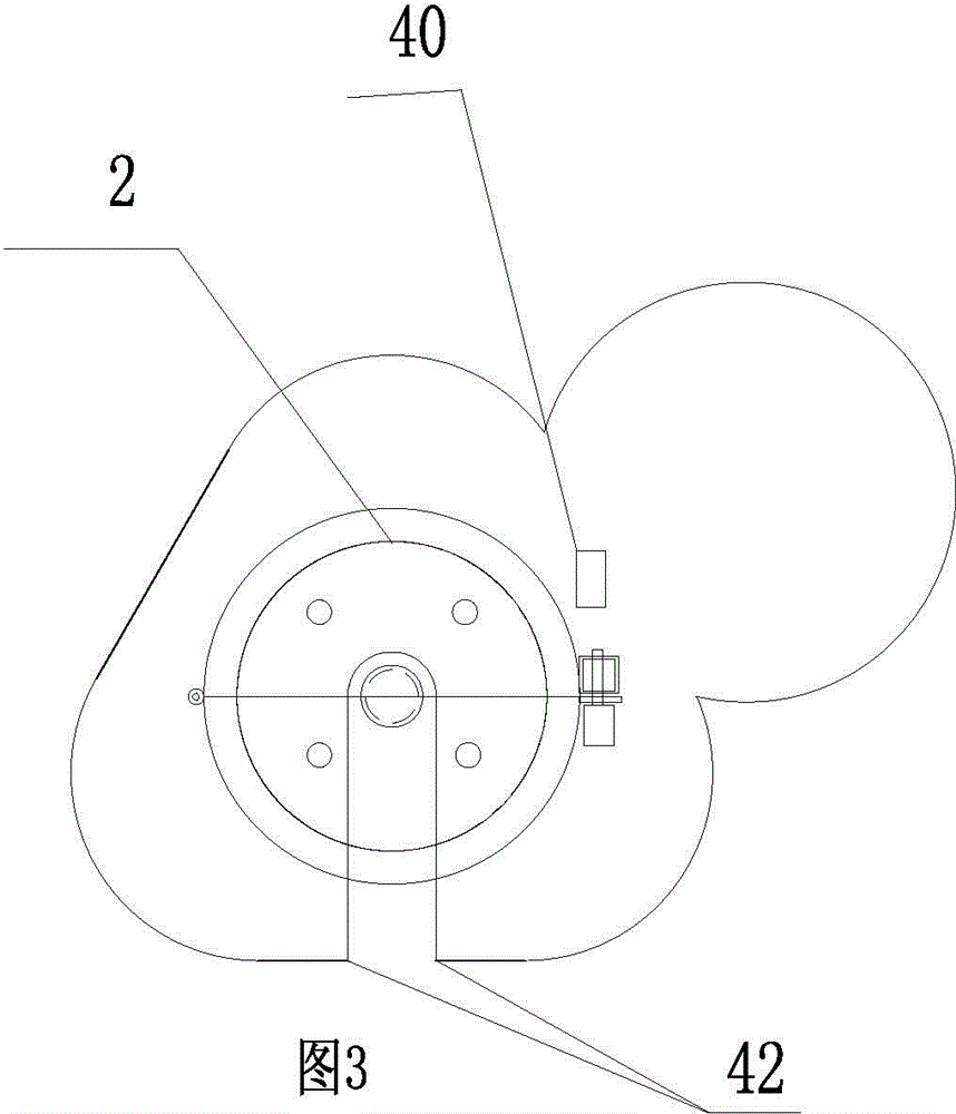
[0023] The present invention as Figure 1 to Figure 9 As shown, the steel wire rope dirt removal and oiling machine includes a cleaning device, a grease injection device, an oil supply vehicle, and a forward and reverse electric hoist is fixed on the upper end of the wire rope. The traction rope of the hoist is connected to the hoisting hook 40 for reciprocating motion, and is characterized in that: The cleaning device includes, spiral type mud removal device 2, inner hollow cylinder 2-1, upper cylindrical sealing plate 2-2, lower cylindrical sealing plate 2-3, upper cylindrical sealing plate 2-2, lower cylindrical sealing plate 2 -3 In the center of the cylinder, there is a hole 2-4 with a diameter of 1mm slightly larger than that of the steel wire rope. Among them, the upper cylindrical sealing plate 2-2, the lower cylindrical sealing plate 2-3 are welded together with the inner hollow cylinder, and then cut in the center and divided into two , and weld the two halves of the...


PUM


Abstract

The invention relates to the field of maintenance of a steel wire rope used in a water conservancy project, a bridge, mine hoisting, a crane ship, a cableway and the like. The steel wire rope 46 is loaded in a cylindrical polyurethane inner hole spiral mud dirt-removing component consisting of two semi-circles; polyurethane hole inner teeth and spiral pitches of steel wire rope strand ditches are tightly rubbed; a spiral mud dirt-removing device moves up and down to extrude mud dirt; three brush rollers 8 are annularly arranged at the inner periphery of a narrow slot opening 6 and are in contact with the steel wire rope 46; a spray type oil nozzle 18 points to the steel wire rope at the inner circle of the narrow slot opening 6; a grease filling device comprises a cylinder body consisting of two semi-circles and provided with a hollow cavity; two semi-circular rubber shaft sleeves are embedded in cylindrical holes; spirals are formed in the inner holes of the shaft sleeves and are matched with spirals of the steel wire rope. An oiling machine reciprocates, can clearly clean and is uniform in oil filling.

Description

technical field [0001] The invention relates to the field of maintenance of wire ropes for water conservancy projects, large bridges, hoisting of drilling rigs, hoisting of mines, marine cranes, cableways, ship lifts and the like. Background technique [0002] The steel wire rope is one of the components of the lifting equipment. It is easy to corrode, wear and chemically attack to reduce the performance. It needs to be maintained regularly. During the maintenance process, dust and sand should be removed and oiled according to regulations. The traditional method is to use manual descaling and grease. Carrying out maintenance, the effect is poor, wasting manpower and material resources, and the descaling and smearing grease is uneven, there will be potential safety hazards. The inventor participated in the design of the steel wire rope suspension maintenance machine, patent number: 201320054504.2. After field tests, it is not possible to use jointless The wire rope is suspend...

Claims


Application Information

Patent Timeline
Patent Type & Authority Applications(China)
IPC IPC(8): B08B1/00B08B1/04D07B7/12
CPCD07B7/12B08B1/00B08B1/32
Inventor 孙有福李学格李辉候磊殷宏曹斌张泗永陆郝玲
Owner ZAOZHUANG FUYUAN ENVIRONMENTAL PROTECTION & ENERGY SAVING MACHINERY MFG CO LTD
Learn More