Laser welding method for cambered stamping part

A technology of laser welding and stamping parts, which is applied in the direction of laser welding equipment, welding equipment, metal processing equipment, etc., can solve the problems of welding through the pot body, the inability to realize large-scale mass production, and large size deviation, so as to avoid being welded through , to achieve the effect of mass production

Active Publication Date: 2015-01-28
HANS LASER TECH IND GRP CO LTD
View PDF6 Cites 11 Cited by
  • Summary
  • Abstract
  • Description
  • Claims
  • Application Information

AI Technical Summary

Problems solved by technology

However, usually the dimensional tolerance of curved surface stamping parts such as kettle spouts is relatively large, coupled with the positional deviation of the clamping fixture, the positional dimensional deviation at the edge of the workpiece after clamping is even greater
According to its material and thickness,

Method used


Image

  • Laser welding method for cambered stamping part
  • Laser welding method for cambered stamping part
  • Laser welding method for cambered stamping part

Examples


Embodiment Construction

[0028] The present invention will be described in detail below in conjunction with the accompanying drawings and embodiments.

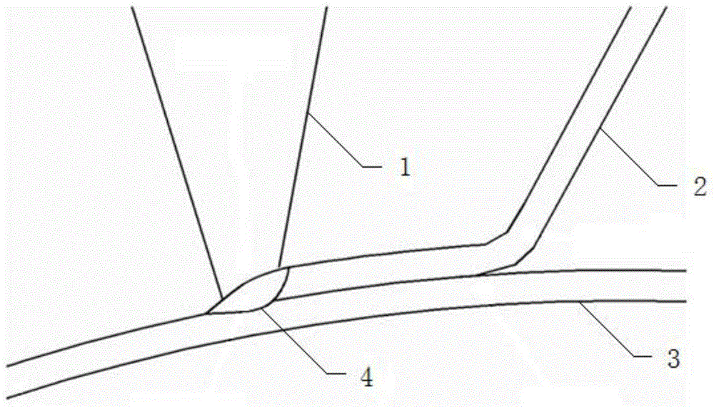
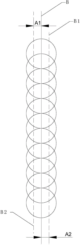
[0029] Such as image 3 As shown, B is the edge of the standard curved surface stamping part to be welded, A1 and A2 represent the position and size deviation between the curved surface stamping part to be welded and the standard curved surface stamping part at the edge to be welded, that is, the actual edge to be welded is located at B1 or B2, The welding trajectory set according to the standard curved surface stamping part is at B. Therefore, if the laser spot is too small to completely cover the position size deviation, it will cause the spot to deviate from the position where the welding should be performed and weld through the workpiece.

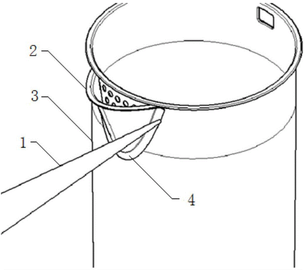
[0030] Curved surface stamping parts usually have a large dimensional tolerance. Taking a kettle as an example, the dimensional tolerance of the spout is about 0.4mm. Coupled with the position deviation of the ...


PUM


Abstract

The invention belongs to the technical field of laser processing, and provides a laser welding method for a cambered stamping part. The laser welding method comprises the following steps: adjusting a laser spot, so that the semidiameter of the laser spot is greater than the position dimensional deviation at the edge to be welded of the cambered stamping part; carrying out laser welding by taking the edge to be welded of the cambered stamping part. Due to the fact that the laser spot is adjusted to enable the semidiameter of the laser spot to be greater than the position dimensional deviation at the edge to be welded of the cambered stamping part, a welding track covers the edge to be welded of the cambered stamping part, the edge cannot deviate, a workpiece is prevented from being welted through, and large-scale batch production is realized.

Description

technical field [0001] The invention relates to the technical field of laser processing, in particular to a method for laser welding curved stamping parts. Background technique [0002] As a new welding technology, laser welding has the advantages of small heat input, high welding strength, and easy automation, so it is more and more widely used. [0003] For the welding of curved surface stamping parts such as the spout and the kettle body, the original resistance welding process needs to be manually operated to complete spot welding, and then manually use glue to further seal the welded joints. There are many processes and automation On the other hand, the use of glue to seal is easy to cause odor in the water body and is not environmentally friendly. Therefore, the original welding process has been gradually replaced by laser welding to reduce the process and realize automatic operation. At the same time, laser welding can be carried out directly. Sealing improves produc...

Claims


Application Information

Patent Timeline
IPC IPC(8): B23K26/21B23K26/60
CPCB23K26/073B23K26/30
Inventor 朱宝华刘昊高云峰
Owner HANS LASER TECH IND GRP CO LTD
Why Eureka
Try Eureka