
Oil discharge device for numerical control machine tool

An oil discharge device, a technology of CNC machine tools, applied in metal processing machinery parts, large fixed members, maintenance and safety accessories, etc., can solve problems such as imperfect oil discharge structure, achieve simple and effective cleaning, simple structure, and oil discharge effect. ideal effect

Active Publication Date: 2015-01-28
TAICANG LIBIAO INTELLIGENT TECH CO LTD
View PDF9 Cites 2 Cited by
  • Summary
  • Abstract
  • Description
  • Claims
  • Application Information

AI Technical Summary

Problems solved by technology

[0003] The technical purpose of the present invention is to provide an oil discharge device for a CNC machine tool to solve the problem of imperfect oil discharge structure

Method used


Image

  • Oil discharge device for numerical control machine tool
  • Oil discharge device for numerical control machine tool

Examples


Embodiment 1

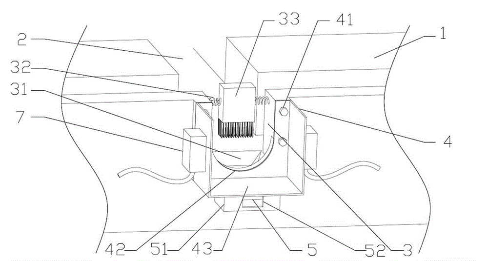
[0017] Example 1: See figure 1 , An oil discharge device for a numerically controlled machine tool, comprising a base 1, an oil guide 2 provided on the base 1, and an oil drain 3 provided on the base 1 for draining waste oil, and also includes a base 1. An oil drain base 4 for collecting and draining waste oil from the oil drain 3, a heating mechanism for thermalized waste oil provided on the oil drain base 4, and a vibration mechanism for urging the waste oil to flow out.

[0018] The oil drain base 4 includes a connecting portion 41 connected with the oil drain 3, a docking port 42 provided at the connecting portion 41 for guiding waste oil into the oil drain base 4, and a storage portion 43 for containing and draining waste oil. The connecting portion 41 can be fixed by bolts or by a snap connection, which is convenient for disassembly, assembly and replacement. The surface of the storage portion 43 is inclined downward. An oil seal layer for preventing waste oil from leaking ...

Embodiment 2

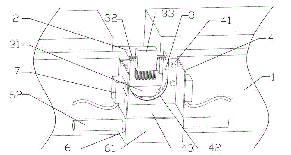
[0019] Example 2: See figure 2 , An oil discharge device for a numerically controlled machine tool, comprising a base 1, an oil guide 2 provided on the base 1, and an oil drain 3 provided on the base 1 for draining waste oil, and also includes a base 1. An oil drain base 4 for collecting and draining waste oil from the oil drain 3, a heating mechanism for thermalized waste oil provided on the oil drain base 4, and a vibration mechanism for urging the waste oil to flow out.

[0020] The oil drain base 4 includes a connecting portion 41 connected with the oil drain 3, a docking port 42 provided at the connecting portion 41 for guiding waste oil into the oil drain base 4, and a storage portion 43 for containing and draining waste oil. The connecting portion 41 can be fixed by bolts or by a snap connection, which is convenient for disassembly, assembly and replacement. The surface of the storage portion 43 is inclined downward. An oil seal layer for preventing waste oil from leakin...


PUM


Abstract

The invention provides an oil discharge device for a numerical control machine tool. The oil discharge device comprises a machine seat, an oil guide passage and an oil discharge opening, wherein the oil guide passage is arranged on the machine seat, the oil discharge opening is formed in the machine seat and is used for guiding out waste oil, the oil discharge device also comprises an oil discharge base element, a heating mechanism and a vibration mechanism, the oil discharge base element is arranged on the machine seat and is used for gathering and discharging waste oil from the oil discharge opening, the heating mechanism is arranged at the oil discharge base element and is used for heating the waste oil, and the vibration mechanism is used for enabling the waste oil to flow out. The oil discharge device has the advantages that the structure is simple, the use is convenient, the heating mechanism and the vibration mechanism are mutually matched, the waste oil is heated so that the waste oil is in a state with higher fluidity in any environment, meanwhile, the vibration mechanism vibrates the oil discharge base element, the waste oil is enabled to flow out, oil slag is enabled to flow out together with the waste oil, a cleaning mechanism can conveniently carry out simple and effective cleaning on positions near the oil discharging opening, the oil discharge effect of the whole device is ideal, and the service life of the equipment is prolonged.

Description

Technical field [0001] The invention relates to the technical field of numerical control machine tools, in particular to an oil drain device of a numerical control machine tool. Background technique [0002] During the processing of CNC machine tools, in order to ensure the normal movement of the moving parts, the oil pump will provide lubricating oil to the sliding track on the machine tool to ensure the normal operation of the CNC machine table and prolong the service life of the sliding track. Commonly used CNC machine tools set up a variety of oil guide channels to drain the waste oil, but when the waste oil is finally exported, it is often simply placed a container at the end of the oil guide channel, and there is no specific and effective oil drainage device for waste oil. Centralized processing. For example, a machine tool saddle disclosed by the invention of Authorized Announcement No. CN 202943436 U has an incomplete oil drain structure, which easily affects the working...

Claims


Application Information

Patent Timeline
Patent Type & Authority Applications(China)
IPC IPC(8): B23Q11/12B23Q1/01
CPCB23Q1/01B23Q11/121B23Q11/124
Inventor 徐丽艳
Owner TAICANG LIBIAO INTELLIGENT TECH CO LTD
Learn More